Hello all…
Ok… First, I am completely new to circuit layouts. But to be honest, aside from possible further mods of what I am trying to create here, I don’t know if it is something I am going to get good at.
I am working on a small project and it needs a little circuit to work.
My project requires the activation of a simple electromagnet several times per second from a low power DC source.
I wish to have it accumulate power in the times that the switch is not closed to get a little more kick to the Electromagnet than just the straight DC power source.
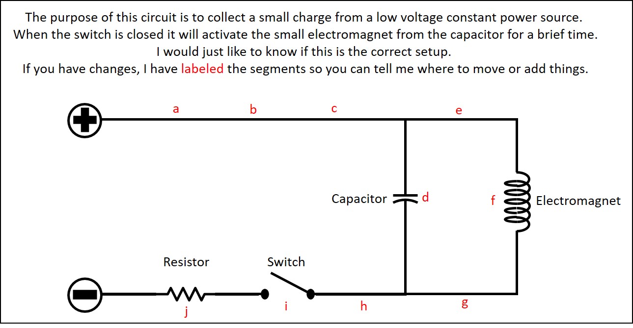
Attached is a diagram of my best understanding of how this simple circuit will work but I would like the opinion of folks more in the know than I.
I would be grateful for any input.
The DC voltage may be variable but I am not expecting more than a volt or two. similar to a AAA battery.
It is not clear if your application requires switching power to the electromagnet a couple times a second or if you are adding the switch specifically to try getting more power to the electromagnet than you would if you just had your DC supply connected continuously. Could you give more details about your overall application?
To achieve the basic thing of charging up the capacitor when the switch is off and then dumping that into the coil when the switch is on, you need to move the switch from location i to location e. Note that this will never give the coil more voltage than you would get from just connecting the battery.
I appreciate the response!!
Basically I will have a small voltage generator. (simple axis/magnets/copper coils) and on this same axis there will be a disk which will activate the switch once per revolution. activating the electromagnet.
If this were a clock, the switch would only be active from the 12 to the 1.
I know that if I just left it raw then the electromagnet would only get current from the generator for that period when the circuit is closed… Which will be to little current and only that short time for any noticeable action from the magnet. and would be a waste of the remaining revolution.
I was hoping to increase the voltage of the short burst output by adding a capacitor and then the current could be collected through the entire revolution. Then released when the circuit is closed making the magnet more effective.
With the switch at node i as you have it in your diagram, the capacitor will not charge when the switch is open. Moving the switch to node e as I mentioned before would cause the capacitor to charge while the switch is open and then help the power supply provide power to the electromagnet when the switch is closed, but I doubt that will have much effect on the strength of the electromagnet. Though, if the capacitor is much closer to the electromagnet than the supply, it might help it energize faster.