Sim Gauges - Hawker Hurricane - Various Mini Maestro - Conunddrum

Morning all. Complete Pololu & Servo noob here.

Excuse the length of the post, but I am having to explain the why’s and wherefores.

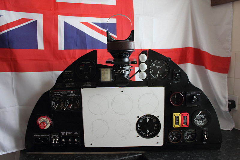
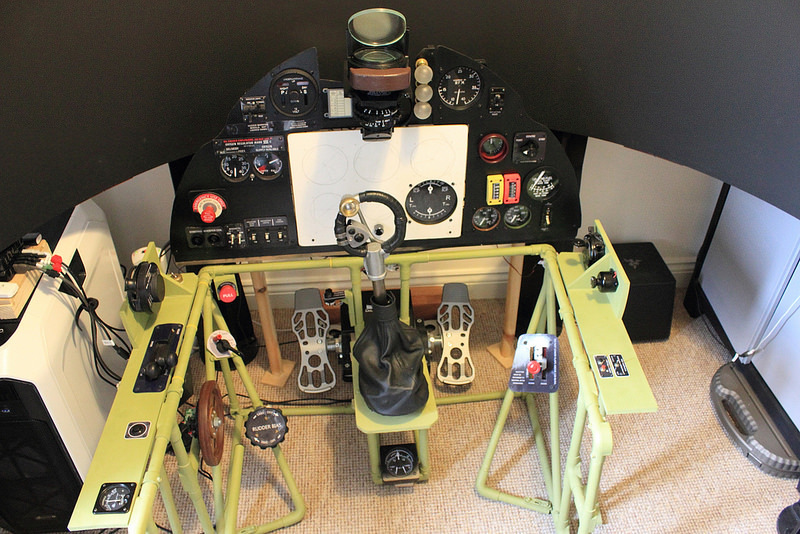
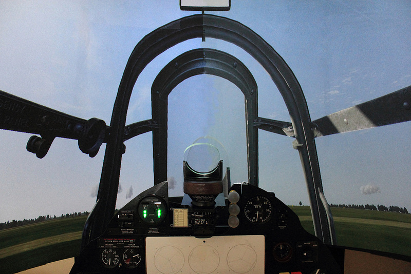
I have cobbled together a 1:1 scale Hawker Hurricane (Battle of Britain fighter) cockpit instrument panel.

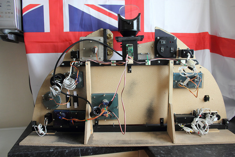
This panel will eventually be home to (possibly, if I include the brake gauge) seventeen (17) individual instruments. All but one (mentioned in a minute) are driven by their own servo’s. Some gauges are driven by more than one servo.

I don’t have all the gauges yet.

I have purchased the following Pololu products:

2 x 6 pin Maestro (to use as required or mix and match).
1 x 8 pin Maestro (to use as required or mix and match).
1 x 24 pin Maestro (being such a noob at this, was rather hoping all my gauges would plug in to this one board.

As noted above. I purchased the 1 x 24 pin under the illusion I could connect all my instruments to the one board. But reading through some of the forum threads. I think I might not be able to provide enough: Voltage or Wiggly Amps, without an external supply.

Could one of you Pololu seasoned vets out there confirm? And if so, point me in the direction of what would be needed to make it work please? Thank you.

There appears to be a subtle difference in manufacturer with regards the servos. I have looked at the Gauges and the Servo makes are: Tower Pro Microserver 9g SG90 & GoTeck GS-9108 Microserver. As mentioned in my opening paragraph. Some of the instruments have more than one servo:

Brake Pressure Gauge = 3 x Servo’s (1 x Stbd, 1 x Port, 1 x Main Pressure)
Turn & Slip Indicator = 2 x Servo’s (1 x Turn, 1 x Slip)
Oxygen Delivery Gauge – This is one complete unit with 2 x Gauges driven by their own Servo’s (1 x Oxy Delivery, 1 x Oxy Supply)

You can see why I went for a 24 Pin Maestro. Naively thinking they would simply all plug in to the one board.

One of the biggest conundrums is highlighted below. I need to try and accomplish the following:

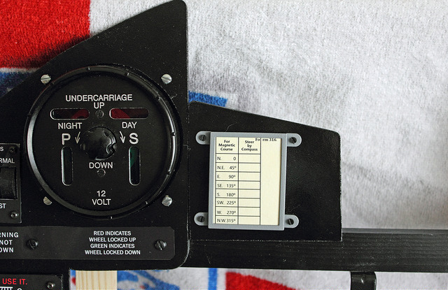
The Hawker Hurricane Undercarriage Indicator is unique to this particular aircraft. The gauge has two vertical Green Indicator windows at the bottom (which has a green LED behind each window). The indicator also house two horizontal Red indicator windows at the top (which has a red LED behind each window)

When the wheels are down and locked, the Green indicator is lit, and stays lit. This will change from Green to red when the undercarriage is raised and the gear locked “up”.

When the wheels are up and locked, the Red indicator is lit, and stays lit. This will change from Red to Green when the undercarriage is lowered.

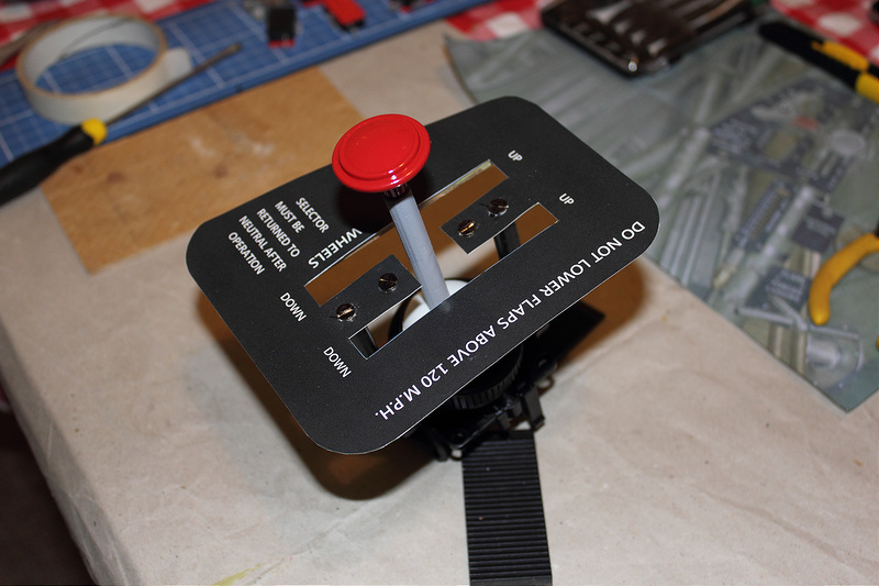
Currently the up/down Keybind (G = Up, CTRL G = Down) is sent to a Leo Bodnar 0836X. This receives the key sent from the microswitch on my homemade undercarriage lever. In game the undercarriage is lowered/raised as per the keys.

How do I tell the Pololu that the gear is down – therefore keep the green LEDs lit (until told otherwise)?

Then tell the Pololu that the gear is up – therefore turn of the green LEDs and turn on the Reds (until told otherwise) when the switch for this is connected to the 0836X?

Thank you to anyone who understands what I am after, and can help out.

Hello.

That sounds like an interesting project! Since you are new, I recommend starting slow and getting small parts of the system working before expanding on it.

You can control up to 24 servos individually with the 24-channel Maestro; but there are a couple of things to consider when powering all of those servos. The traces on the Maestro power rail can handle about 6A; if the combined current draw of your devices is larger than this, we recommend splitting the power rail into separate banks by cutting the trace designated by the dotted line in the picture below:

Splitting the power rail into separate banks allows you to use multiple power supplies, which could also be useful for using servos with different voltage ratings.

Additionally, each header pin can handle around 3A, so if the current draw of a single servo is greater than 3A, we recommend powering the servo separately from the Maestro board. Please note that you will still need a common ground with the Maestro to complete the signal circuit.

As far as the indicator LEDs for the landing gear, it sounds like you have some kind of switch that extends and retracts the landing gear. You might be able to use that as an input to the Maestro and write a script that controls the LEDs accordingly. You can find information about connecting a switch to the Maestro in the “Button or switch” heading of the “Attaching Servos and Peripherals” section of the Maestro’s user’s guide. By the way, how are those LEDs being driven (e.g. are they part of a larger system or are you trying to control them directly from the Maestro)?

Brandon

Good morning Brandon,

Thank you for your reply. I will be attempting to give it a go this weekend.

I thought a few photos would help you visualise what I am trying to do. Or at the very least see how it all “connects” together.

Firstly. Here is the unique Hawker Hurricane, Gear & Flap leaver (this is homemade using some dowel, a drawer handle (painted red) and an underarm deodorant bottle and finally a label made in MS Publisher). The Lever always starts from neutral (in the middle).

To aircraft will start on the ground, lever in Neutral, but the gear would be down (2 green LEDs on the U/C Indicator). Taxi out. Take Off. To raise the undercarriage, put the lever in the Up position, this activates a microswitch, connected to a Leo Bodnar 0836X. The Gear raises, and the 2 green LEDs on the U/C Indicator go to 2 red LEDs, indicating the gear is up and locked.

Here is the Hawker Hurricane unique U/C Indicator (handbuilt) in my homemade cockpit panel. Hoping this photo helps you visualise the gauge. What it does. And the LED relationship.

Here is a photo of my panel so far, with some of the servo driven gauges installed. The white BFP (Blind flying panel) does not have the Climb & Descend, Directional Gyro, ASI, Artificial Horizon or Altimeter fitted yet.

Here is the back of the panel. 24 pin Maestro behind the Gunsight.

Finally, the instrument panel and frame (which houses the Gear & Flap H-Lever), so you see how it fits together.

Here is a shot of the U/C Indicator showing the lit LEDs (Gear Down). The LEDs are drawing power from the Bodnar 0836X. I would prefer to let the Maestro take charge.

I will take a photo later today, of how the LEDs are wired up. They have the 3 wire normal servo pins on the back of the LEDs. I presumed they would connect to the Maestro, and wait for Up/Down state to be sent by the board.

Thanks once again.