


Hello, I recently purchased the shunt regulator (Shunt Regulator: Fine-Adjust HV, 4.10Ω, 15W
), but I wanted to use it for a slightly different application than intended. Rather than having it discharge small voltage spikes, I wanted to use it to regulate batteries that have independent BMS’ that are connected in series. I am not worried about their under-voltage thresholds, however, the over-voltage, I wanted to mitigate any voltage drift over time by having the shunt regulator dissipate a small amount of current within the power limits over time. However, the device itself doesn’t have a designated current limit built in to ensure 15W isn’t exceeded. My initial plan was to use a resistor to limit the maximum amount of current that could be sinked, however, I am now realizing that this will lead to oscillation due to the shunt regulator not having a 4-wire kelvin connection to distinguish between battery voltage and current limit. Are there any adjustments that can be made to limit the amount of current and have an accurate activation threshold with hysteresis without the risk of oscillation?
Hello.
In general, these devices are designed to dissipate larger millisecond pulses generated when a brushed DC motor controller slows a motor down, and not for dissipating a small load over the long term . We have not thoroughly characterized the response frequency for these devices; however, I can offer a few tips if you want to experiment to try to find something that works.
Rather than adding a current limiting resistor in series with the board, it might be possible for you to replace the shunt resistance on the board with a larger resistance so that the control circuit still sees the full voltage on the line. This is a simplified schematic diagram that shows how the shunt resistance is connected on the device:
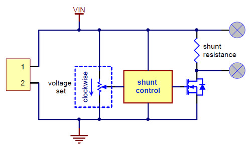
It sounds like you already have the board, but this version of it with minimally populated shunt resistors might make the modification easier.
What sort of power and at what voltage do you expect to need to dissipate? Also, what is the power source to the battery?
Brandon
Hi Brandon,
That makes sense. The battery is a 24V with a max voltage of 29.5V. There would be 2 in series for a 48V system charger. The charger is a regulated output from an MPPT charged from solar panels. Out of curiosity, what type of solder is used and how what is the thickness of the copper on the boards. From testing, the boards get quite hot when dissipating a small amount of current so I am assuming taking components off would require a decently large soldering iron.
The power I was looking to do was about 30W at 29V with a 25-ohm resistor (inline). Otherwise, to keep the power under 15W, I could use 55-ohm resistor to replace the ones on the board. Is the 15W a limitation of the MOSFET or the heat generation? Or was that meant to be a pulsed rating rather than a continuous rating?