Sharp Sensor GP2Y0A60SZ mystery fluctuations

I am trying to get as clean of a read as I can out of this sensor and am running into two things I’d like to delve into to see if I can improve the reading.

  1. I’ve put a 10uf capacitor across V+ and Ground to try to smooth out the voltage. It has had minimal effect. Is there a further way I can condition the voltage? At any range, analogue read seems to fluctuate up to 70 values constantly in analogread. Is there a way I can further stabilize this?

  2. Also there is an interesting reality that I’ve tested with two of these sensors and had the same result:

When its powered and running and I put one of my fingers near the back of the sensor I can drop the anlogread value 80. I intend to use this sensor in a way that I can’t guarantee if a human hand will be within the 1.5 inches behind this sensor that seems to effect it’s reading. The closer I get the lower the read in analog read if I touch the edge of the board it drops about 100. Im assuming this is some sort of emf but I’m sure someone more qualified in the way of electrical wizardry can tell me why this is happening. Is there anything I can do to compensate for it?

Thank you for your help and assistance

Kabe

Hi, Kabe.

It is hard to say whether the fluctuations you are seeing are normal, since you did not give the actual amount you are getting in Volts. However, it looks like you are using an Arduino to read the sensor’s analog output, which would make your 70 units of fluctuation about 350mV. In my experience, that amount of fluctuation doesn’t seem unusual for this sensor. Also, placing a hand behind the sensor might be causing slight fluctuations in the amount of ambient light on the surface, which could affect the sensor’s readings. I suggest implementing some kind of averaging on the output to help filter out the fluctuations. You might also try using a larger capacitor (a couple hundred micro farads would probably be good).

If those don’t help, you could post more about how you are reading the sensor and pictures of the conditions that you are testing it in and would be glad to see if there is anything else I could suggest.

-Nathan

I’m still trying to solve best I can the natural fluctuations which like your saying may be normal for this sensor. However one thing that I believe makes this sensor difficult to rely on is the drastic fluctuation when any type of antennae like object is behind it.
I believe if someone looks into can be easily reproduced and may be an issue with this sensor, I’ve purchased two and have the same result with both:

Placing my hand or body near the sensor isn’t changing the ambient light it’s still a proximity thing I still believe relating to emf. The readings can drop over 100 which from the data curve is a fluctuation of about 3/4 the full range of the sensor so those variations render it near to almost useless for me. Trying to get more precise as to what is going on I grabbed my long metal pointy tool. As I bring it towards the back of the board the voltage fluctuates accordingly and trying to find a particular spot I’ve noticed it specifically for the top right 4ish pins:

One of those pins in the top right corner is a beacon for wild interference. And I don’t mean it happens when I touch it or poke something near it, it occurs when your finger, or some sort of antennae approaches the sensor. You can see a drop shift in readings when touching the top edge of the board, and a larger drop shift when your finger gets near, without touching, the back top right corner.

I’ve done this with two different sensors, and I plan on using this near hands so this makes this unusable for me as far as I can tell. I trust this can be confirmed and I wonder if there’s a way to work around or patch fix it. I have high hopes for this sensor I’m hoping there’s something I can do.

Another thought: Could this shifted drop in voltage be that an antennae is clearing an emf interference in the reading that is happening all the time? And if so can I introduce something that intentionally introduces the presence of something to maintain this down shift in readings?

Any ideas?

Hmm per someone’s suggestion to ground tin foil behind it and see if it changes anything that seems to fix the issue completely.

The finished project will be going into an enclosure. Will an enclosure with a grounded piece of metal mounted behind the sensor be the most efficient resolution for this?


Hello, Kabe.

Hmm. That’s very strange. I tried replicating the antenna effect with a similar setup here and was unable to. I even tried using a battery for power instead of a computer’s USB plug to see if eliminating any possible common ground with the building would cause the problem to appear. If the foil shielding seems to work for you, a grounded metal shield in your final project might work. I have run into issues with very high impedance inputs (20Mohm) acting strangely in a metal building before, though these IR sensors should not be that sensitive. You might also want to try finding a common ground with the building your project is in.

-Nathan

Strange we’re getting such different readings. Thank you for taking the time to try to recreate it in the first place.

So…After hearing your comment about power source laptop or battery I suspected the laptop sending in some odd voltage or something so I cut the vcc & ground wires from my usb cable and to make sure I was just running it off the lipo. Same thing, same readings.

So. I’m going to make a video to share, maybe someone can tell me whats going on.

What you see on my breadboard:

Video messed up half way so there’s 2 parts. Also correction: I say I spliced Source and ground on USB cable. I meant to say I cut them so they are disconnected cleanly so as not to provide feedback as mentioned above.

Video Part 1
Video Part 2

For clarification the numbers are the raw analog readings without any filtering, delayed by 100ms.

Thanks again to anyone who’s spent any time answering these questions on the forum. Rock on

Kabe

Hey Kabe,

That foil loop seems to be making a difference. For my test setup, I was using one of our A-Star Prime 32U4 LV boards, which has an LCD screen attached. I was printing an average value and the difference between the maximum and minimum values for sets of about 500 readings taken over a one second time period to the LCD screen rather than using the serial monitor. It might be useful for you to use some code that performs some averaging of more frequent measurements so you can see if the average value is about the same when you move your hand closer. Here is some averaging code I used to test some things out today.

//Statistics library from http://playground.arduino.cc/Main/Statistics
#include "Statistic.h"

long timeSerialUpdateIncrement = 1000;
long timeStatsUpdateIncrement = 10;
long nextSerialUpdate;
long nextStatsUpdate;
Statistic myStats; 

void setup()
{
  myStats.clear(); //explicitly start clean
  nextSerialUpdate = millis() + timeSerialUpdateIncrement;
  nextStatsUpdate = millis() + timeStatsUpdateIncrement;
  Serial.begin(115200);
}

void loop()
{
  if (millis()>nextSerialUpdate) {
    Serial.print("a=" );
    Serial.print(myStats.average());
    Serial.print(" c=" );
    Serial.print(myStats.count());
    Serial.print(" s=" );
    Serial.print(myStats.pop_stdev());
    Serial.print(" m=" );
    Serial.print(myStats.maximum());
    Serial.print(" m=" );
    Serial.println(myStats.minimum());
    myStats.clear();
    nextSerialUpdate = nextSerialUpdate + timeSerialUpdateIncrement;
  }  
  
  if (millis()>nextStatsUpdate) {
    myStats.add(analogRead(A0));
    nextStatsUpdate = nextStatsUpdate + timeStatsUpdateIncrement;
  }  

}

It is interesting that your USB connection kept working even with the ground and power wires disconnected. However, in general all the grounds in your system should be connected, so you might try reconnecting the USB ground wires.

I see you are getting raw readings around 180. I am not familiar with the Teensy and its analog functions. Do you know what voltage that corresponds to, in millivolts? If I recall correctly, the Teensy is capable of 16-bit precision on the analog pins, but I’m not sure how that comes through the Arduino analogRead() function. Is there a specific reason you are using the 5V version of the GP2Y0A60SZ sensor? You might want to verify that the Teensy can handle inputs greater than 3.3V on the analog pins.

-Nathan

UPDATE: When I touch the grounded foil the readings are OK, they drop only slightly when I put my finger real close. If i’m not mistaken this is just showing that the problem is I’m static-ey. Is there something I can cover the board on the sensor with to protect it from this kind of electrostatic interference? Or do I need to make sure nearby human hands are grounded?

From your eyes does it look like this is (put my finger too close to it) interference is something in the board/sensor itself? And do you think it’s something I can rectify (preferably without a faraday cage)?

I do have some averaging code I’m pretty happy with, I actually brought it back to analogread just to eliminate the perception that my code might be somehow to blame. In my averaging code although it helps smooth it out but with the added interference of bringing a hand nearby the drops are dropping but maintain consistancy to give a stable false average. About half of my measured curve is over the span of ~63 values. So there isn’t a large enough spread to not have this drastically mess up the measurements. When I’m measuring 30 inches for example without interference it’s fine but with an object getting close to those pins in that area a drop of 63 brings the reading to 60 inches which easily happens. :frowning:

Yea I was curious if that was going to work. It actually didn’t effect the values so I have since replaced it with an un-butchered cable.

[quote]
I see you are getting raw readings around 180. I am not familiar with the Teensy and its analog functions. Do you know what voltage that corresponds to, in millivolts?[/quote]

180ish seems to be around 60-62 inches (Onto matte white paper surface ~ seemed to give most stable reading)
Lemme check… 180 / 1023(max read from 3.3v) * 3300mv = 580mv

First I used the 3v sensor then I noticed the mention on the 5v page I can run the 5v at 3v for more accurate distance at the end of it’s range. Which turned out to not only be true for more accurate long distance but was true for more accurate everything readings (by this I mean it provided a cleaner (steeper) curve to determine distance). The teensy is 5v tolerant on input so I checked to see if the accuracy of the curve would be any different driving it at 5v. It wasn’t, which I’m finding odd, so I’ve now replaced it with a 3.3v voltage regulator with the near-same IR output.

I’m curious now why analogread wasn’t much different when driving it at 3.3 then driving it from the 5v step up regulator… I measured inch by inch and the average readings were for all real purposes identical… I just got the multimeter out to test the voltage regulator output. Solid 5v. Replaced with 3.3v regulator. Solid 3.3 volts. OK.

Teensy readings coming out of the sensor: still relatively identical - about 180 @ 60" 1023 @ 4". How can this be?

Both seem to be about 180 at 60 inches and max 3.3v at around 4 inches. Is this normal?

Thanks again,
Kabe

Edit: After posting this I familiarized myself with the fluctuations more, and have come to the position that this must be protected from electrostatic.

I recorded another video to show the effectiveness of the shielding and during, I noticed that the top left pins make the readings jump UP.

So the spread between potential electrostatic fingers near the top left of the board and the top right is up to 275 which towards the end of the distance is a variation of about 40 inches on my curve.

You mention getting 1023 at 4" with the 5V sensor. On the Teensy, it sounds like 1023 should be 3.3V. I would expect that if you have a sensor outputting a voltage over 3.3V, it would still read 3.3V (1023).

Does the antenna effect occur at shorter measurement distances? You might try to simplifying your power supply to see if that helps with the antenna effect. The easiest setup would be to try the 3.3V sensor with the Teensy using the only USB power and supplying the sensor from the Teensy’s 3.3V pin. The sensor draws 33 to 50mA, so you would need to double check to make sure the Teensy’s onboard regulator can supply that current.

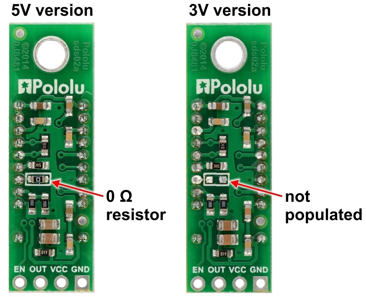
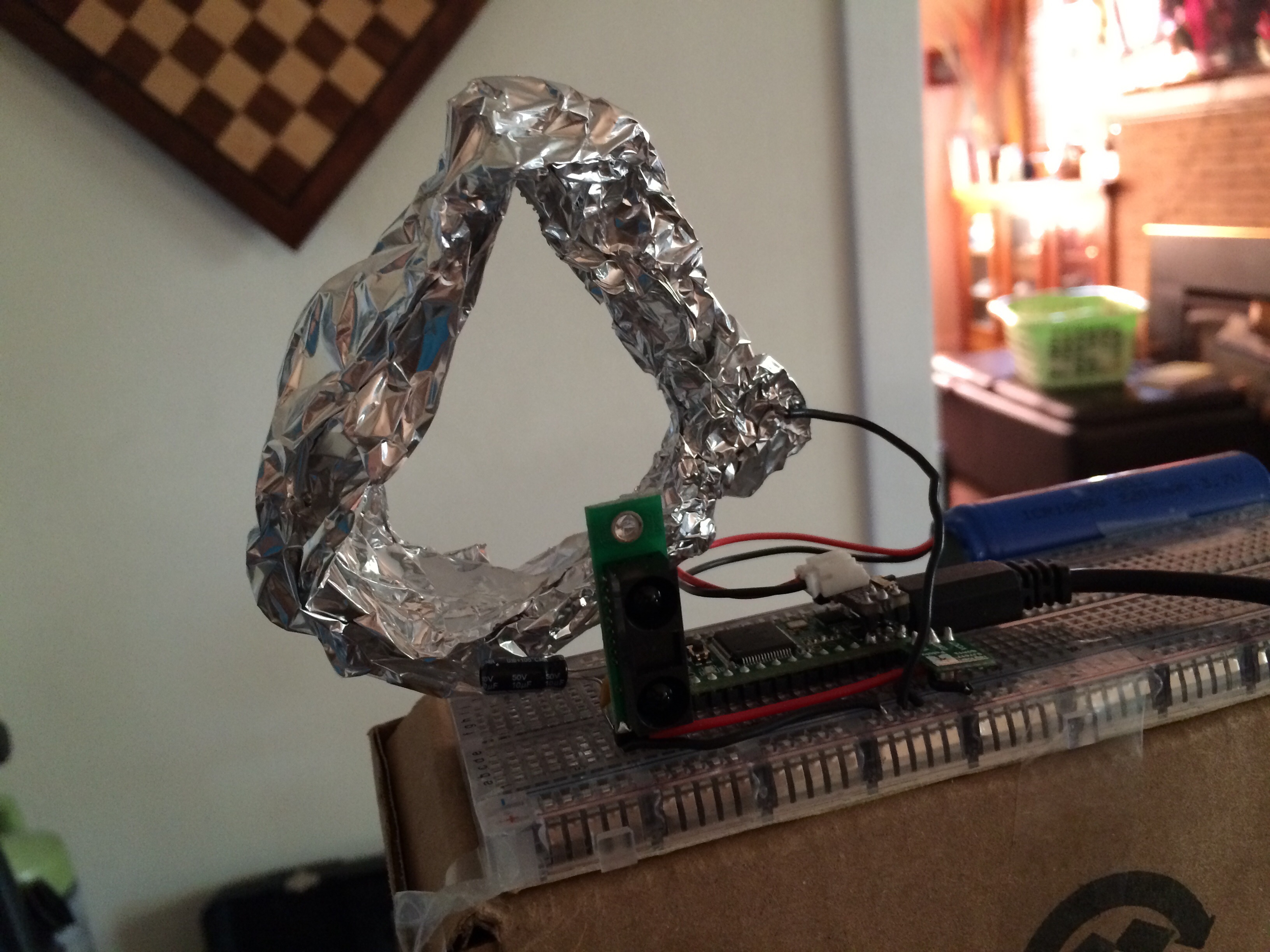
Update: The antennae effect is only with the ir sensor. One (or more) of the pins on the top left of the board and top right of the board are effected by electrostatic interference. I’ve since wrapped it in grounded aluminum tape (insulated from the IR sensor) and it nullifies the issue completely giving me more accurate readings when something is nearby and more accurate readings all around even when nothing is nearby.

I also mentioned in one of my videos earlier that there’s a random blip I assumed was coming from the teensy and I would have to deal with that, unfortunately it looks like that too is coming from the IR sensor itself.

So since wrapping it in aluminum, I’ve plugged it in to read the raw reads with the ir reciever covered with electrical tape (to get true 0): I now get a solid reading most of the time of 2, 3, & 4 (NICE!)

However… I’ve focused my sights on pinpointing the consistently timed blip, and I’m wondering if I can get more information about it.

To pinpoint the fluctuations I first tried to isolate it:

Test 1: See if it’s the sensor by removing the sensor and plugging the analog-in pin into ground.
Result: Consistent reading of 2-3 no blip
(So the blip is in the sensor unless it’s in the supply voltage and passing through the ir sensor)

Test 2: See if its the supply voltage by plugging the supply voltage into a 2 15ohm resistor voltage devider (to get a reading below 1024) and then into the analogread pin
Result: I get a solid 533-537 which is well… close to half 1024 (max read and represents 3.3v) … but nevertheless, is stable and means my variation is only ~12mV.

Sounds good. Still no blip, the blip must be in the IR sensor:

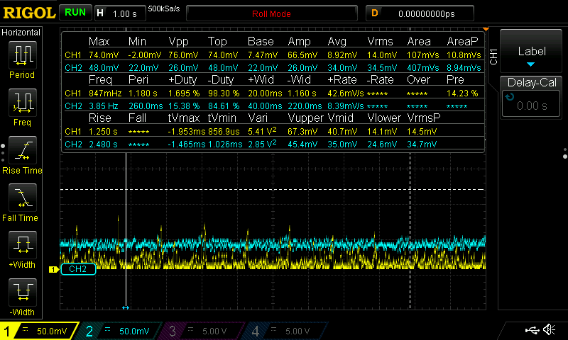
Plugged the ir sensor back in with the ir reciever covered in electrical tape the readings are mostly 2-3 still (exactly as they should be.) but the perfectly timed voltage blip is back:

It’s a very consistent and perfectly timed pulse of 8 voltage spikes. The voltage spike is always ~350mV and the 8 (i assume bit) pulse happens ~66 times a second. This seems like processing feedback from the ir sensor itself, given the perfect timing, spacing and always 8 blips. I doubt there is a way to nullify this before dealing with it in software but I’m curious if pololu is aware of it. ~66 x8 = ~528 ~350mV blips a second, given it only mucks up a sliver of time but it would be good to avoid it. Any idea if this is improvable without just working with it in software?

That being said I have a feeling the answer is going to be “So what, deal with it.” - beggars can’t be choosers.

I’ll deal with it in my averaging, but thought I’d share at this point: here’s raw feed with the IR reciever covering 1 second. If you put it in a good text reader like sublime text you can get a visualization of it if you zoom out and see the one digit values turn into 3 digit values during the blip. Its a perfectly spaced pulse of 8. So this isn’t just random interference and it’s coming from the sensor with certainty since this test immediately follows me taking a constant reading of 2-3 from analogread of ground and then an analogread of my voltage source with only a variance never outside of 12mV. Also I’ve double checked that the ir sensor aluminum tape shielding I’ve added is not a variable producing this issue. I have a 2nd pololu ir sensor without the shielding that produces the same 8 pulses.

Thanks again for all the help and input it’s great being able to have a conversation while working on this and in the end I hope it might help others.

Oh also if anyone else is reading this: the capacitors going over voltage and ground seemed to do nothing for me so I’ve removed them. Besides the issues detailed above, and the static interference issues the caps weren’t necessary and the readings are clean and consistent without them.

Kabe

Hello, Kabe.

I’m glad to hear you found a solution for the antenna effect in your system. I took some oscilloscope measurements using a sensor I set up and I saw peaks of about 500mV without an extra electrolytic capacitor in the circuit, but adding a 470uF electrolytic capacitor next to the sensor reduced them to about 200mV. The refresh rate of that sensor is 60Hz, so I suspect that the blips correspond with bursts from the IR emitter.

-Nathan

I think I might be experiencing a similar issue. I’ve found the output from my sensors to vary quite a bit in the same conditions, but mostly, when there is no object to detect, the noise from the sensors makes it difficult to return a “no object found” status to my microcontroller code.

I actually purchased an oscilloscope recently to help troubleshoot this issue (so I’m pretty new to using an oscilloscope just fyi :slight_smile: and I was just trying to get an output that was stable when no object was present like when an object is present.

Here’s what it looks like, do you think this is the same type of fluctuations the OP posted, or do I have another issue entirely? Also, I was trying two sensors, and a single sensor as well, the two sensors are obviously having some sort of interference issue with each other, but the single sensor is noisy too. I had a 22uf electrolytic cap across the VCC and GND terminals of both (and the single) sensors.

When there’s an object present there’s almost not fluctuations at all in the measurements, they’re very consistent, just a continuous nice even line. Also, it seems pretty odd but on the scope the measurements show up as discrete values rather than a range of voltages… They look like dots in the picture above, but I used several different modes and they were all flat lines varying in steps. Maybe that’s normal?

Another oddity is that both these sensors are pointed across a large room with nothing in their path (angled away from each other) and they’re reading different values. You’ll notice the labels on the left for Ch1 and Ch2 are at the same offset, so I’m not sure why they’re coming in so different from each other.

I can take additional pics or measurements if needed.


Hello.

It is normal for those sensors to have more noise on their outputs when there is no object to detect within their range. Is there a reason averaging measurements over a few seconds will not work for your application?

-Nathan

Well I had purchased them mainly for their high polling rate, if I average the results I’d actually be looking at the data over two points instead of one which seems like my effective sample rate would be halved?

My particular application requires the highest sensor response time possible, so I was hoping to find a reliable way to detect an object as quick as possible without false positives.

I’m currently having a hard time finding a voltage threshold that will work for more than one sensor since they report different voltages and over a wide range when no object is found.

Hi.

From the screenshots that you posted it looks like the spikes of noise you are seeing are happening about every second, so if you averaged many readings over that second, you could reduce their effect. For spikes like that, sampling more often than the 60Hz refresh rate of the sensor would probably allow you to reduce the noise and keep a high effective sampling rate. To keep your program responsive, you might also consider using a moving average.

These sensors are mainly meant to be used to determine the distance to an object within their 10-150cm range. The datasheet for the sensor does not guarantee any specific behavior when there is no object in that range, so If your application depends on finding a reliable threshold value between the sensor detecting an object at the very end of its range and not detecting an object, this sensor might not be practical to use.

-Claire