I encounter some issue with my project.
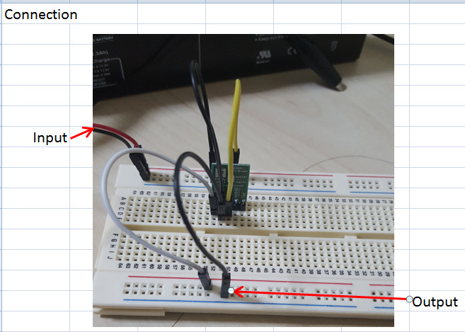
I using D24V10F6 (pololu step down regulator) to step down my voltage from 12V to 6V. My connection is disable PG and SHDN. GND was connected to (12V) source’s ground and also output’s ground. Vin was connected with 12V and output was measure as 6V which is the voltage that i need.
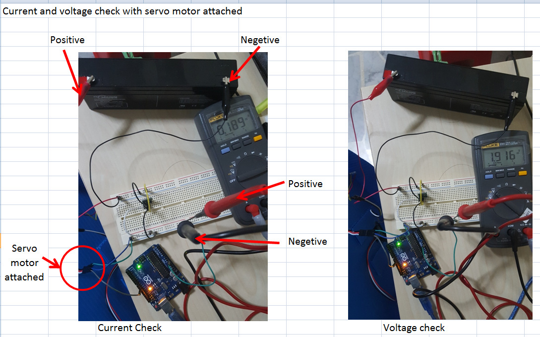
The issue occur when i connected with servo motor (SM-S4315R) to the output voltage (6V). Servo motor did not rotate but it vibrating without moving, and the voltage measurement is only 1.8V.
Can anyone please help or advise on this issue.
Please let me know is there any additional information that you need to allow you guys give a better picture.
Based on your description, I suspect that your servo is drawing more current than what the D24V10F6 or power supply can source. Can you measure the average current draw of your servo using a multimeter (or ampmeter)? To get an idea of the performance of the regulator, you can look at the efficiency graph under the “Typical Efficiency and Output Current” section on its product page.
I also suspect servo motor drawing more current than what the output current provided.
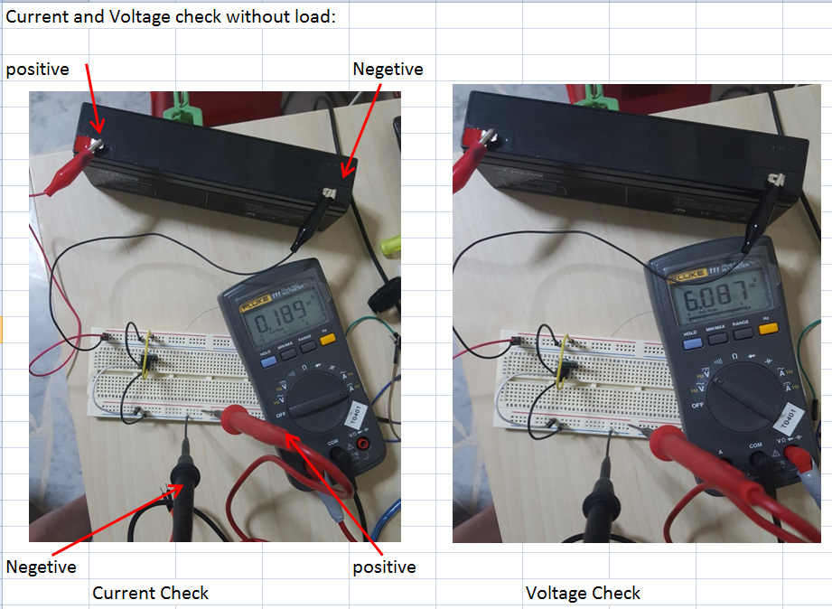
Im using 12V, 2.3Ah seal lead acid as my source. I checked my output current is only 0.185A with and without load attached. Suprise me that output current drop so much and i kind of curious why it droped that much. Will it because of i did anything wrong with the connection? I though it suppose to be around 1A.
My servo motor ave current is around 150mA ~160mA. According to it data sheet, it did not indicate servo motor peak current which i did not take it to account.
It seems strange that the current draw does not increase with a load. Did you take that measurement while powering your servo from the regulator? Can you post a picture (or a video) showing how you are measuring the current?
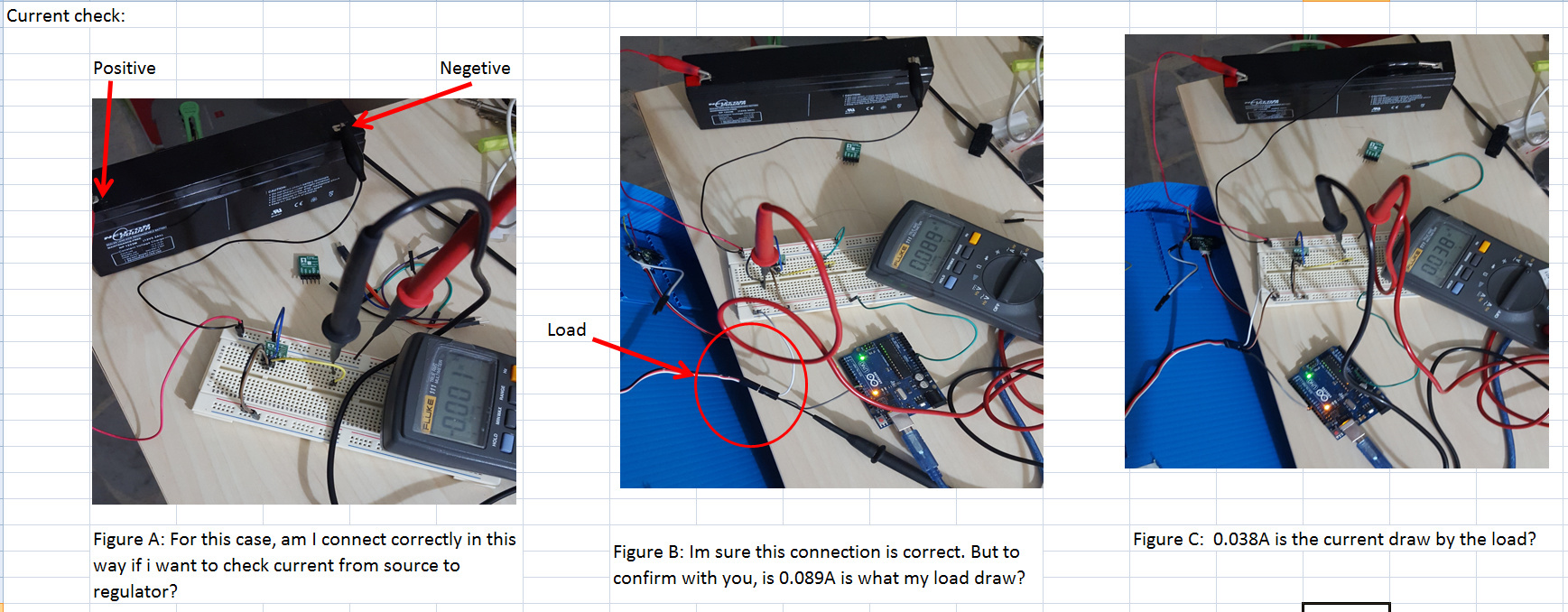
Thanks for the pictures. You are not measuring the current correctly. Essentially, you are shorting out the power output by connecting the two probes across VOUT and GND of the regulator. To measure the current, it needs to flow through your multimeter, so you need to place the two probes in-line (or in series) between the regulator and load. I did a quick Internet search and found this video on how to measure current with a digital multimeter, which might be helpful.
The measurement taken in the first picture (from the left) looks correct, but I am unable to clearly see the connections in the other two pictures. I suspect that you are still measuring the current wrong, considering that the servo current draw reading is still quite low. Regardless, I do not think that you will be able to accurately read the maximum current draw of your servo without using better equipment.
At this point, I suggest using a 4.5V to 6V battery pack (4 or 5 AA batteries would work) to power the servo to make sure it is working. If after that you still want to use the 12V battery as your projects power supply, you might consider getting a more powerful step-down regulator.
I’m having similar problems with the 6V up/down regulator and the Maestro 6. Actually, I had the vibrating problem with the 5V u/d regulator and now nothing with the 6V. Stand-alone, the regulator is delivering 5.55V. Plug it into the Maestro 6 and it drops to 1.95V. I use a 6V alkaline battery pack and it maintains the voltage. The 6V regulator is being driven off of a 5V 2A wall wart. Sadly, analog electronics aren’t my thing.