So I’m trying to utilize serialization using the Arduino IDE to create command prompts for 2 stepper motors that utilize the T825 microcontrollers.
For example, if I type into the console:
Motor1 moveDown
The expected output should be that the first motor should move down for a certain period of time. If you’re familiar with Tic.h, the following should occur.
However: I can’t seem to get motor1 (less alone both simultaneously w/ motor2) to work physically.
In the examples provided by Pololu in their GitHub, I was able to control both of the motors simultaneously (I2CMulti example).
I’m assuming that if the motors were able to run in the example code for I2CMulti, then they should also be able to run my program.
If someone could assist me through this process of being able to run at least 1 of the motors using serialization and I2C communication, that would be great.
I’m using Arduino IDE 2.0.4, as well as tic.h version 2.1.1.
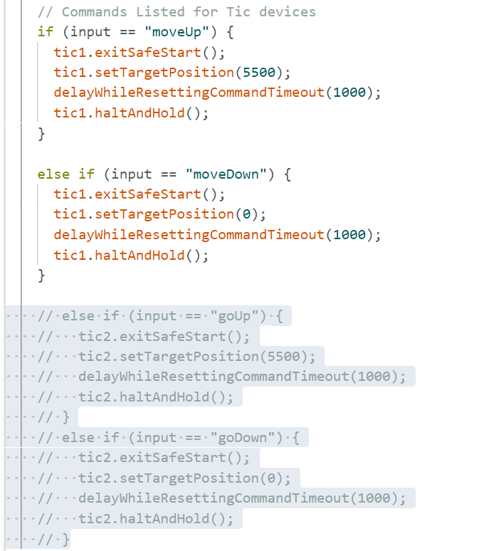
I suspect your Tic is triggering a command timeout error (which also triggers the safe-start feature). So, you can probably get it to work by adding exitSafeStart() commands before sending the setTargetVelocity() commands. For example:
However, we generally recommend only using the existSafeStart() commands as a response to a user action (i.e. starting up the system or pressing a button); otherwise, it does not provide the same intended safety benefits. So it is probably better to address the issue directly.
By default the command timeout is set to 1 seconds, so it will be triggered if the Tic does not receive certain commands for a full second. Our I2CMulti.ino example uses a custom delayWhileResettingCommandTimeout() function that sends the resetCommandTimeout() function continuously while delaying. You could do something similar, or you could adjust the command timeout length (or disable it entirely) from the “Input and motor settings” tab of the Tic Control Center.
Thank you, Brandon. So I took your feedback and implemented into the code. Fortunately, one of the motors now work to perfection. On the other hand, I can’t seem to get the second motor working using the same implementation. What could be the reason behind it?
I do not see why that wouldn’t work from the code snippet you posted. Is the second Tic indicating an error with the red LED on the board? If so, could you connect it to the Tic Control Center and check the “Status” tab to see which error that is?
Also, could you post your complete updated code, as well as a copy of the settings file for each Tic (clearly indicating which is which)? You can use the option under the “File” drop-down menu of the Tic Control Center to save a copy of the settings file for the connected Tic controller.
There is no error that is being presented with the motors. Right now, I am able to fully control the two motors. However, I am not able to make each motor run separate.
For example:
In my code,
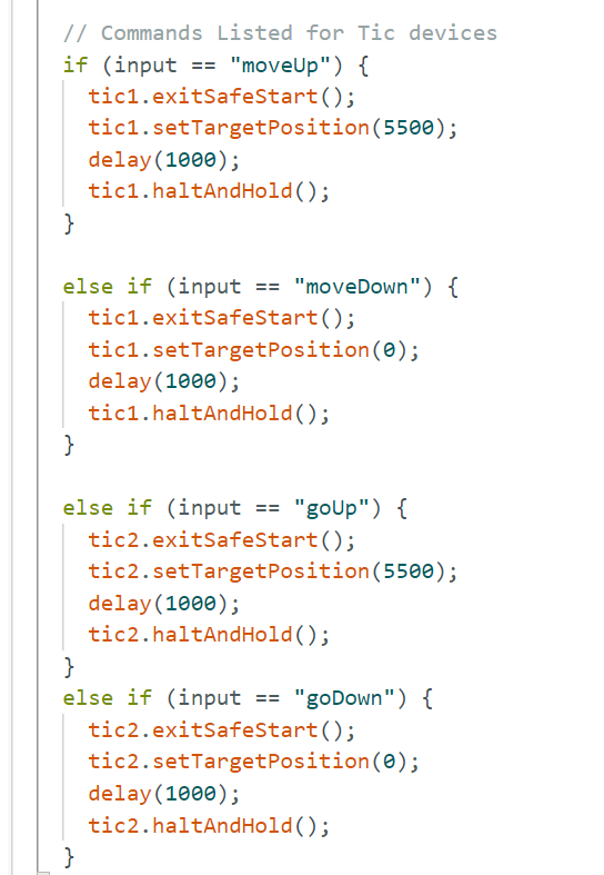
Input “moveUp” results in both of the motors moving in their positive direction.
This problem is also featured when I input “moveDown”, in which both motors move in the negative direction.
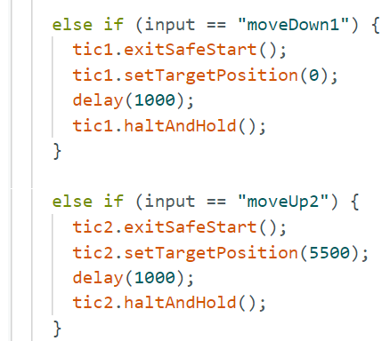
For some reason, inputting “goUp” and “goDown” will not call the following conditions tied to it.
(For reference: “moveUp” and “moveDown” should correspond to Motor 1 (tic 1)
“goUp” and “goDown” should correspond to Motor 2 (tic 2)
Goal: Run each motor according to their inputs.
Problem: Both motors run on Motor 1’s inputs…
I am glad to hear you found the problem; thank you for letting us know what it was.
It looks like you’re using one of our other boards as a stand-in for the Tic in your diagram, so I’m going to assume the blue and yellow wires are going to SDA and SCL like you described. Is there a reason you’re using pull-down resistors on the SDA and SCL lines? By default, the Tic pulls those lines high. If your application requires speeds faster than 100 kHz or so, then you might even need to add a strongly pull-up.
As far as the power, I would generally not recommend powering the Tics/stepper motors through your Arduino’s Vin pin, since it is probably not sufficient for that kind of current draw. Instead, you might consider powering the Tics directly from your power power supply and powering the Arduino’s Vin pin through the VM pin on one of the Tic controllers. The VM pin gives access to the input voltage after the reverse voltage protection circuit. If you need a way to break out the connections to your power adapter, you might consider something like a DC Barrel Jack to 2-Pin Terminal Block Adapter.