
I have a receiver circuit that is magnetically coupled via a parallel resonant circuit with the sender (similar to RFID but just one directional). I want to feed the signal into an ADC which has, according to the datasheet, an input impedance of around 5 kOhm.
I measured the voltage across the resonant circuit with an amplitude of about 60mV when using an oscilloscope that has an input resistance of 1 MOhm. Obviously, the measured voltage is going to be a lot less when using the low input resistance of the ADC. This is why I decided to use an impedance converter before the ADC:
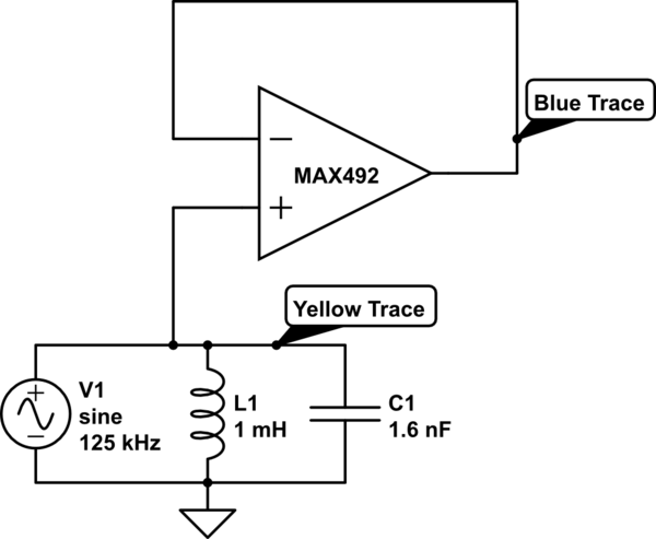
simulate this circuit – Schematic created using CircuitLab Note: V1 isn’t an actual voltage source, it’s just there to point out that there is a voltage induced there. The opamp is powered from +5V.
When measuring the output voltage of the impedance converter, I get a signal that is very chopped up like so:
Measurements
I’m using a MAX4026EWP+T: http://www.kynix.com/Parts/3951508/MAX4026EWP%2BT.html Opamp. The parameters I took into account were the Gain Bandwidth Product as well as Slew Rate:
Gain/BW Product = 500 kHz, so it should be able to amplify the 125 kHz Signal by a factor of 4. In the impedance converter setup, the gain is 1 so this shouldn’t be the problem.
Slew Rate = 0.2 V/us, the 125 kHz sine wave has a rise time of 14∗1125kHz=2us14∗1125kHz=2us. So the Opamp should be able to change the Voltage by 400 mV in that time.
Is there something I’m missing with this particular opamp or is my approach just wrong in the first place?
I’d appreciate any help.