S7V8F3 Buck/Boost Shutdown Behavior

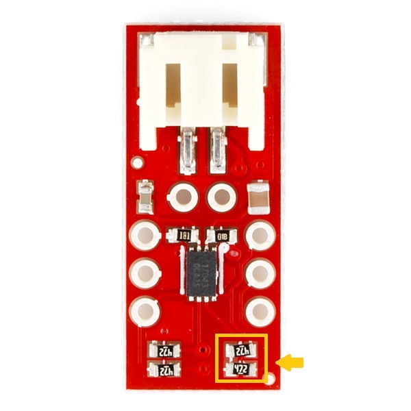
When S7V8F3 is in shutdown mode, SHDN pin tied to ground, what is the expected voltage level on the output pin?

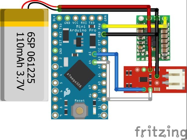
The reason I ask, is that I have a single cell lipo 4.2 V as my power source.
When the regulator is active, I read 3.3 V on the output, but when the regulator is shutdown, I read 1.2V on the output?

I would expect this to be 0 V, especially if the “Load is disconnected from the input”, as stated in the datasheet.

Device Enable
The device is put into operation when EN is set high. It is put into a shutdown mode when EN is set to GND. In shutdown mode, the regulator stops switching, all internal control circuitry is switched off, and the load is disconnected from the input. This means that the output voltage can drop below the input voltage during shutdown. During start-up of the converter, the duty cycle and the peak current are limited in order to avoid high peak currents flowing from the input.

Hi.

When that regulator is disabled the output will be disconnected from the input, not driven low. As the schematic for the regulator shows, there are some resistors between the output and ground, so generally the output will be pulled down, but it might be possible that something else in the system is causing a voltage on the output or that it is taking a while for the residual voltage to drop (due to capacitance in the circuit, for example). What do you have connected to the output of the regulator? Do you still see a voltage on the output if you remove the load from it? How are you measuring the voltage on the output and how long after shutting it down? Can you post pictures of your setup that show all connections?

-Claire

Thanks for your thoughts.

I’m measuring the voltage of the output by placing a DMM parallel to the output and ground.
And i’m using this S7V8f3 Buck/Boost Schematic.

While testing the regulator without a load, when shutdown mode is triggered, voltage starts to drop, and it takes ~40s for the level to drop to 5mV. This is consistent with your explanation of residual voltage drop due to capacitance.

The loads I have connected are, an arduino pro mini and a sparkfun fuel gauge.

If I just have the arduino as the load, shutdown seems to work fine.

But when the sparkfun fuel gauge is in the mix, the buck/boost VOUT rests around 1.2V in shutdown mode.

To figure out what may be the problem, I studied the schematics of my loads.

The fuel gauge schematic shows the I2C (SDA, SCL) lines are being pulled high, via VCC, which is connected to the regulators VIN and the battery (necessary to read the battery level).

The arduino pro mini schematic shows the I2C (A4-SDA, A5-SCL) lines are also being pulled high, via VCC, which is connected to the regulators VOUT.

So it appears that when the regulator is shutdown, the I2C lines are powering the regulators VOUT via the pull-up resistors on the fuel gauge.

To fix this issue, I removed the pull-up resistors from the fuel gauge. (see image)

Now, the buck/boost regulator can shutdown with the fuel gauge connected.

I am glad you found the issue and were able to modify your board to address it. Thanks for letting us know.

-Claire