I’m using the Romi 32U4 control board and I’ve got a much more powerful SBC mounted instead of a Raspberry Pi. This SBC can’t actually run off the 500mA of a standard USB port - it needs at least 1A.
From reading section 3.5 of the control board user guide, I thought this would be OK - that I’d be able to draw up to 2A (when running on battery power).
I’ve got my SBC wired up as if it were a Raspberry Pi, with its power coming via RPI5V. I assumed RPI5V and 5V (i.e. the output of the TPS2113A power multiplexer circuit) were the same thing? But RPI5V seems to max out at 500mA rather than at 2A.
I’ve connected up an Adafruit INA219 high side DC current sensor breakout in order to monitor the current during the SBC’s boot up - all goes well with current consumption rising steadily during the process until it hits just over 500mA for a fraction of a second, at which point the SBC shuts down
Should I connect my SBC to VREG? I guess there’s no point connecting it to the 5V output (that can switch between VREG and 5V USB) as my board can’t use the basic 500mA of USB. You may ask why I don’t simply try this but everything is fully assembled now and I’ll have to take it all apart and solder a connection to VREG first - I’d like to know in advance if this is pointless, i.e. if VREG will provide no more current that RPI5V?
And one more question - the user guide says 2A should be available from VREG. Am I right in thinking this is all that’s available to everything powered off the control board, i.e. the 32U4 MCU, the encoders and in particular the motors and the SBC?
The stall current for the 120:1 mini plastic gearmotor, that the Romi chassis kit uses, is listed as 1.25A. Does this mean if the Romi bumps into a wall, i.e. comes to a sudden complete stop with both motors going at full power, that the two motors together will try to consume 2.5A, i.e. more than the 2A total VREG can supply? Will the SBC then lose power every time the Romi bumps into something? Sorry if I’ve misunderstood the meaning of stall current.
Here’s a graph showing current consumption over the course of the boot process. The x-axis is time - at about the 10s mark I turned on the Romi control board - it’s powered by 6 NiMH AA batteries (all fully charged - I’ve checked) and there’s no USB power to either the control board or the SBC. At the 10s mark, you can see the voltage (orange) jump to 5V and then current consumption (blue) increases (on the whole) over the course of the boot sequence. Then at the 37s mark the current peaks at 514mA (just as the board tries to turn on WiFi) and then the SBC shuts itself down (I’m assuming because it can’t draw enough current - it boots fine when powered via a 5V 2A source).
In general, I expect you to be able to get nearly 2 A from the RPI5V output, so I’m not sure what’s going wrong in your case. I did a quick test and had no problem drawing about 1.25 A from RPI5V.
RPI5V is the 5V voltage after it passes through an additional ideal diode circuit (so that an externally powered Raspberry Pi doesn’t backpower the control board), but that shouldn’t limit the current available. Connecting your SBC to VREG would bypass both the power mux and the ideal diode circuit; I don’t expect it to make much difference, but it might help if:
your SBC is especially intolerant of undervoltage conditions; taking out some of the stuff between VREG and RPI5V might reduce the drop in voltage that they incur
the spike of current is actually significantly higher than 500 mA (if it is, your current sensor might not be fast enough to capture that). If the spike is much higher than 1.5 A, the power mux’s current limit might be kicking in and causing it to lower the voltage.
If connecting to VREG does help, removing your current sensor might also make a difference; it looks like it uses a 0.1 ohm current sense resistor (which should drop about 50 mV at 500 mA).
As for other things that might be consuming current from VREG, note that the motors are not powered from the regulated voltage, so the current they draw doesn’t reduce what’s available from VREG.
What SBC are you using? Could you post a picture or diagram showing how you have it connected?
As always I’m super impressed at the support I get whenever I ask a question on the Pololu forums. Thank you
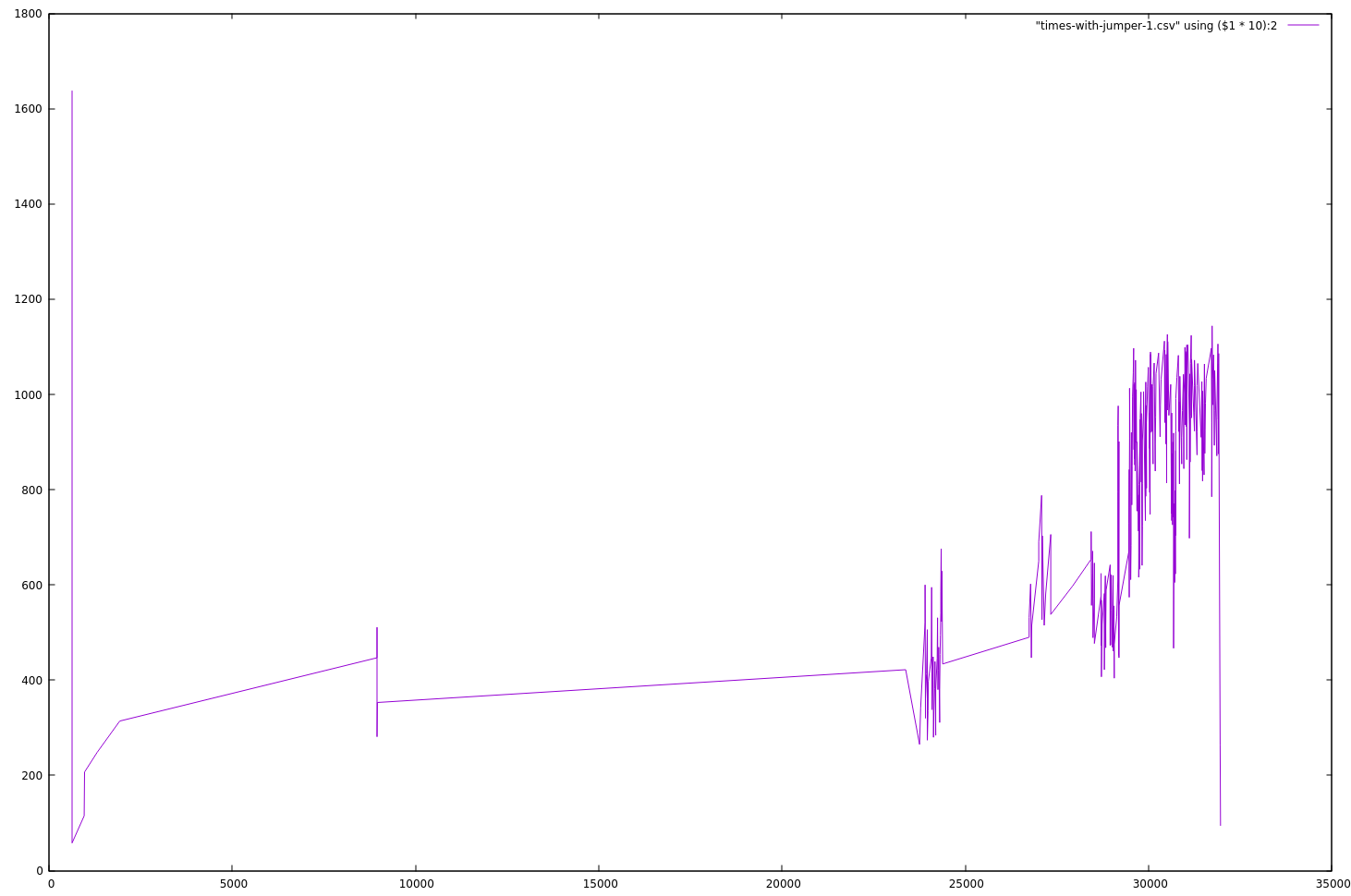
You are correct that my current sensor wasn’t catching the peak of the spike - so the 500mA figure was incorrect. I did a little more experimenting (with fairly crude equipment) and, according to the best measurements I could get, the SBC momentarily draws about 1600mA when it first starts, before immediately falling back, to then rise gradually during the boot sequence to a high of about 1200mA at which point the SBC shuts down unexpectedly.
After a lot more experimentation the problem seems to have been the jumper wires! Up until now, I was using 150mm jumper female/male wires from Adafruit.
Then I tried solid core 22 AWG copper wire - cutting off 20cm lengths and just stripping off the coating for the male ends and crimping on terminals myself for the female ends. This worked perfectly - the SBC got through the complete boot sequence without any issue!
I also tried some 75 mm jumper female/male wires from Adafruit - these work fine too, the SBC boots without problem (but 75mm is too short for use in the final setup that I want).
The 75mm wires were bought at a different time to the 150mm ones and look distinctly different - they feel cheaper and thinner than the 150mm ones but they work and the 150mm ones don’t.
I was surprised and unconvinced that it was just the wires - but I tried different wires out of the two packs and the behavior is consistent - the SBC always shuts down at about the same point in the boot process (enabling WiFi) when using the 150mm wires and booted properly with the 75mm wires (or my self made 20cm solid core wires).
So everything works now - I’ve ordered some 150mm jumper wires from Pololu for the future (and will treat the Adafruit ones with suspicion from now on - though to be fair they seem to work fine at the lower currents common in most hobbyist projects).
I’m glad to hear you figured it out. We’d be interested to hear if the Pololu jumper wires make any difference; they are slightly thicker than the Adafruit ones you linked to (26 AWG instead of 28), so that might help reduce the voltage drop through them. Another possibility could be that the connectors on the end of your wires were not making good contact or had high contact resistance.
The Pololu wires arrived yesterday and I’ve just had a chance to try them out today. They’ve worked perfectly without any issue at all
Like you suggested, I suspect poor connections may have been an issue - the connections between the female ends of the old jumper wires and the male pins on the SBC seemed very solid but the jumper wire male pins are quite thin and they didn’t feel so solidly in place in the female header of the 32U4 control board. The situation was even worse with the 22 AWG wire that I used (until I introduced little wrinkles in the ends by bending them back and forward with a pliers).
I’m happy with the Pololu wires now but still, I think I’ll end up soldering them onto the control board (and leaving the connections to the SBC as they are). This will make for a stronger connection and it makes sense anyway as I’ll solder the power wire to VREG - at the moment if I power the control board via USB (to upload a sketch) then the SBC also powers up only to brownout once it sees it can’t draw enough current (which obviously isn’t ideal).