Rotate and Lift Shoulder

I am trying to figure out how to rotate and lift shoulders on a full scale humanoid.

Hobby servos would fit inside the arms, but they do not have enough torque, so I purchased Torxis Servos with 1600 oz-in (115 kg-cm) of torque.

These are too big to fit in the arms - if only they were cylindrical…

So I must use them in the torso.

Does anyone know how to make shoulders both lift and rotate while the servos are in the torso? The problem is clearly entanglement.

I have patented this collar bone schematic to try to solve the problem but its hard to find the parts I need to build it.


I would love to see alternative methods because all the arms I can find on the internet use little servos for little arms. Also, direct links to the required parts would be great. The shoulder on its own has become a very difficult task inside my mannequin:


pololu.com/product/2375

If these little 490 oz-in servos provide enough torque, they might fit inside the shoulder. Besides, they’re only sixty bucks each compared to my monster servos for $290 (plus $150 delivery).

Does anyone think these are better suited to my project or will they be too weak? Also, they require 9 Amps each. I’ll probably use 14 of them if they are powerful enough. That’s 14x9=126 Amps.

Anyone know a good 6v 126 Amp power supply? I don’t know what Amps are, so I’m wondering if an infinite amount of amps is fine to use. 4 AA batteries only have 4 amps or something, correct?

Also with my monster servos, I might use them to rotate the base plates for each mannequin. They’re 12V 4A. So should I get a 12 V power supply with a 6V reducer or use 2 separate power supplies? Also, do voltage reducers affect amperage?

Thanks for your help :slight_smile:

I found this image for a lamp arm which does not consider rotation on any segment (but the pivot point on each segment allows for maximum torque, which is good):


And then I found this robot which looks like it has a good shoulder design, but unfortunately the rotation motor is in the shoulder which would not be allowed in a sexy mannequin shoulder (it doesnt increase the weight of the arm though, which is good):


I have redrawn my shoulder system on photoshop:


I would love any suggestions on improvements.

I would recommend a hydraulic ram or an actuator, both can easily be made, the first requires a lathe or a welder, you find 2 pipes one pipes fits inside the other and is a shorter length, the shorter length has each end closed(welded) and with a lathe (optional) cut a groove at one end for an O ring or weld some tags to hold the O ring, this becomes the piston of the ram.
Of course your driving power is pressure , but your hold torque becomes compression.

An actuator is nothing more than a thread and nut (can be more complex) and simple the driving force is the motors rotation, you holding torque is the nut and rods thread.

The ram has less complexity and also less accuracy the flip side is the actuator has higher accuracy & more complexity (chatter).

If speed is not necessarily desired but accuracy kind of is, then a worm drive might be a better (cheaper) option, Mitsubishi make the BEST! worm drives for the Magna series of cars more to the point the electric window drives. $5-10 from a wreckers is the norm , they are configured as right angle to the worm drive , they have no SLOP! , and the stator on the worm is only pressed and glued, therefore easily removable or left intact there is enough shaft inside the motor housing.

I flew to Jakarta and picked up some of these power supplies this morning, but they’re only 33.3 Amps each (this is only enough amperage to power three of the servos I included in my post above plus a microcontroller). Also, I’m not sure how Adjustable Switching Regulators really work to split power supplies into 12v and 6v. Can anyone help me understand how to wire these together to get the right amount of amps and voltages? There’s definitely not going to be much room in the torso so there will either have to be a wall, backpack (not!) or a power lead going up the legs. Besides, I think power supplies need ventilation, right? This is my first robot project so if anyone has built a robot before, please help. Thanks ;D


[quote=“jb_norman”]I would recommend a hydraulic ram or an actuator, both can easily be made, the first requires a lathe or a welder, you find 2 pipes one pipes fits inside the other and is a shorter length, the shorter length has each end closed(welded) and with a lathe (optional) cut a groove at one end for an O ring or weld some tags to hold the O ring, this becomes the piston of the ram.
Of course your driving power is pressure , but your hold torque becomes compression.

An actuator is nothing more than a thread and nut (can be more complex) and simple the driving force is the motors rotation, you holding torque is the nut and rods thread.

The ram has less complexity and also less accuracy the flip side is the actuator has higher accuracy & more complexity (chatter).

If speed is not necessarily desired but accuracy kind of is, then a worm drive might be a better (cheaper) option, Mitsubishi make the BEST! worm drives for the Magna series of cars more to the point the electric window drives. $5-10 from a wreckers is the norm , they are configured as right angle to the worm drive , they have no SLOP! , and the stator on the worm is only pressed and glued, therefore easily removable or left intact there is enough shaft inside the motor housing.[/quote]

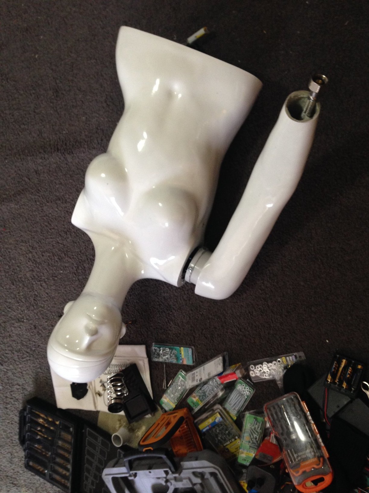
Thanks JB. I thought about linear actuators but they look very, very slow in the videos I saw. My mannequin wants to move at human speed (preferably dancing speed). Having said this, my current design uses so much cable because I don’t trust the shoulder pivot screw with a firmly attached pulley to the upper arm on a belt-to-servo system to be light enough to simply rotate. If it does, that would be awesome, because I fear that my long cables will really slow her down, and I will need to modify the Torxis servos so they can wind cable reliably. This in itself is problematic because the Torxis horn is attached via a weak clamp that you can loosen with an allen key but the shoe tightener snaps so easily yet the horn cannot be removed. If I can’t get the horn off then I can’t open the damn thing to cut the rotation stopper off the potentiometer.

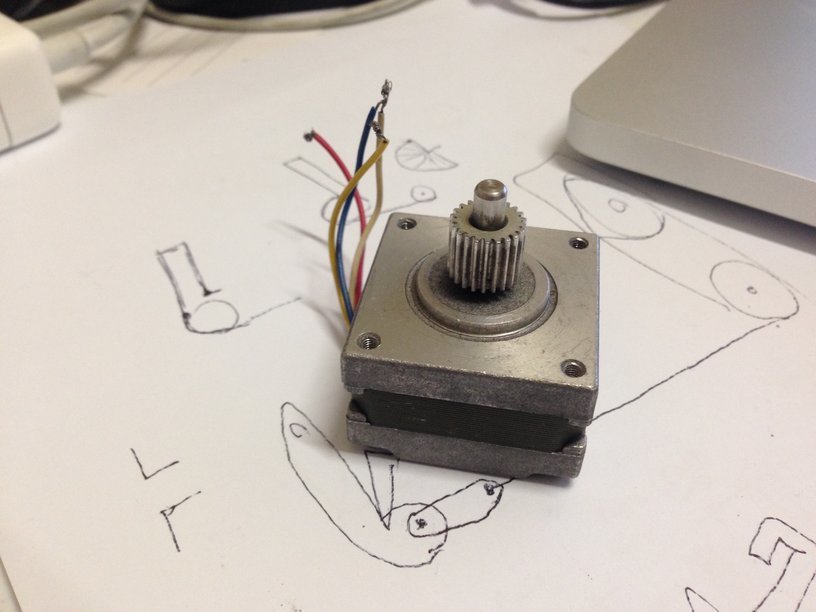
As for hydraulics, I think they would be noisy and I would need to abandon all my work so far. I am curious about stepper motors, because at least they are shaped in a semi usable way (unlike the ridiculously useless shape of servo motors):


I love the cheapness of stepper motors from car wipers and windows from wreckers, but I would love to know that I just didn’t waste so much time and money on what I’ve done so far.

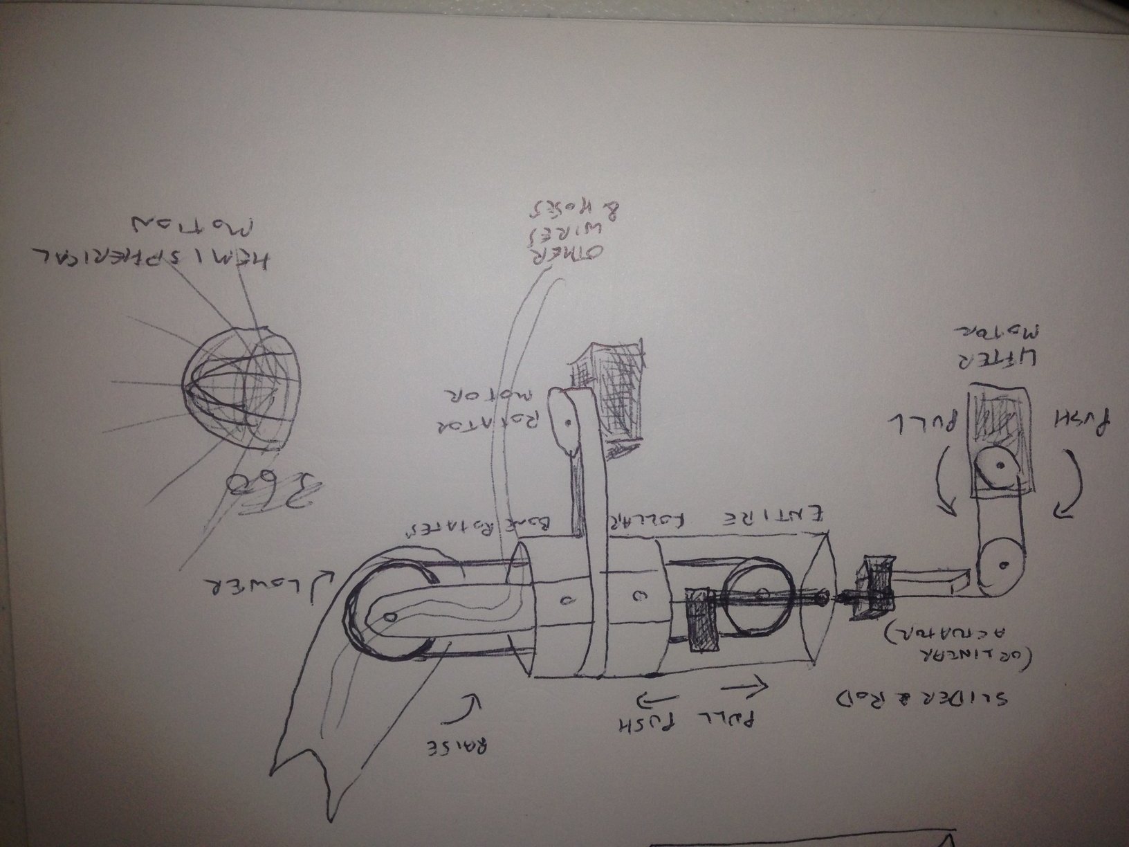
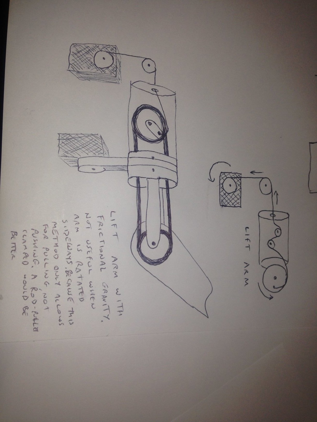
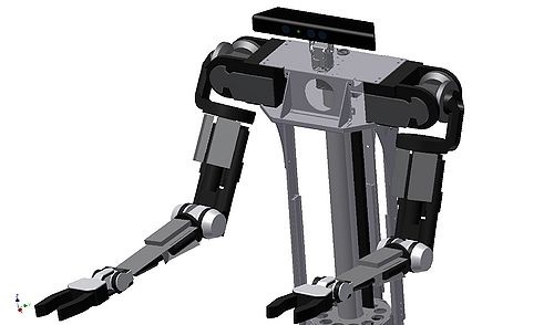
The thing that still needs to be addressed is how to make all the torque I need fit inside a female mannequin arm. The torso seems like the obvious place to store the servos, but then cables and belts get twisted and stretched as appendages pivot and rotate because servos are stupidly shaped like asteroids. My invention of the exterior flexible shaft for rotation with an interior wire for leverage has some potential (and should revolutionize robotics if I do say so myself - the rotation of this bendable hose is brilliant because the shaft bends but twists accurately across very long distances - my guess is 15 metres per millimetre of unwanted twisting - like a giant bolt that snakes around as many S bends as you like with a hollow centre for lubricated cable / wire /nitonol. This is similar to using a Dremel flexible shaft in the same way as riding a donkey is similar to driving a formula one car. The shaft’s exterior is the rotating part - at least one hundred times stronger than a dremel flexible shaft, which is flimsy, unreliable and it cannot pull and rotate in a single shaft). But I still don’t like it because it relies on counterbalancing with springs instead of a firm push-pull control. I’m trying to avoid springs (except maybe for pivot screw tensioning so that servos don’t throb when bearing weight or simply fall and smash things when power is lost).


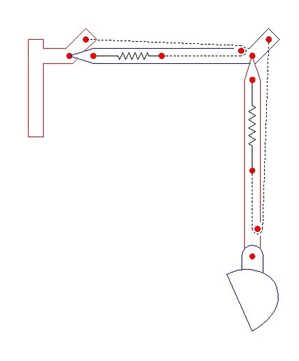
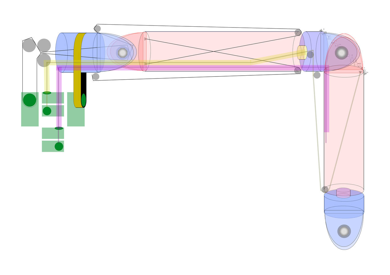
In my photoshop image in an earlier post I used the yellow and magenta lines to illustrate the use of these external metallic thread shafts as rotators attached to one servo with a pull cable down the centre of each shaft attached to a second servo. This would work a lot better if there was some kind of highly bendable rod that could be sent down the middle instead of weak cable so I could use it to both push and pull. Maybe I should investigate Nitinol Muscle Wires some more. I can’t think of anything other than string that could be thin enough to loop through the centre of the flexible shaft. String would friction itself to dust as it sawed back and forth past itself, and putting a divider inside the shaft would be very difficult. I guess I could PVC-sheath and lubricate a single direction of string to prevent friction decay. But then there might be a traffic jam. I just need fast, high torque, cylindrical servos but they are always weak, stupidly designed or massive and expensive.

Something that seems to move a lot faster than car windows is automatic doors on shops. What motors do they use? They don’t even require counterbalancing, do they? Not like a drawbridge or elevator. Sewing machine motors are fast. I wonder if they could be controllable using a microcontroller to run with servo accuracy. Having said that, all the microcontrollers I’ve seen for sale are capable of only one sequence with no menu options, unlike every robot toy for sale, which allow you to choose quite a large number of sequences with sound effects. I’d use CD servos which are found dumped outside everyone’s house these days as part of old desktop computers, but they are only capable of blinking as far as my robot is concerned.

There a three definitive’s i always adhere to, Planning , Budgeting & Cost. One must always consider the order of these & from these a solution can always be expediated.

It can be size, weight & cost. Cost is the fixed variable it can be time, dollar value or any finite resource.

Every Plan has a budget, every good plan has a budget.

Your budget defines the parameters of your plans.

Every project that fails or is never finished is the result of poor planning or poor budgeting.

Good planning, is planning everything in smaller stages, these stages are the gross product of the plan & that said you can visually see which stage needs to be reduced or expanded based on your budget.

Do all of these things & research more.

Btw Hydraulics can be silent!

I’m planning now. I need to know how to do it so I know what to buy. Everything needs to fit inside the mannequin. The initial budget for my prototyping will be higher than for my next robot when I can buy all the parts I need quickly. I don’t mind if people give me realistic solutions that will cost too much money - at least I will know what solutions are best.

I just need answers to my questions above. I’m glad to know hydraulics can be quiet, but I know it can be done with servos. My questions are about the mechanics of my servo robot. I would love to use 100% 6v servos but I have done some testing and none of them have been powerful enough. The 12v servos are much stronger…

I thank you for your responses though. I thought maybe this forum wasn’t being used.

I found this power supply that saves me a lot of wiring hassles. Its only 20 Amps but at least it has a 6v-12v switch. There must be more sensible power supplies out there like this:

I will use my 12V/33.3A wall socket power supply from the previous photo and then attach one of these step down convertors to convert to 6V/20A. From what I am guessing, this will allow 13.3A for my 12V/4A Torxis servos and 20A for my 6V microcontroller with all my other servos plugged into it.


amzn.com/B00J6ODWTM

I might need to find some higher amp power supplies, or start getting street smart about which servos I choose next time. If I need to alter the amp split, there also 5, 10, 15 and 25A step down convertors available.

I hope my power supplies have regulators built in, and that the voltage on this step down convertor doesn’t alter when I am drinking from the 12V pool.

This video shows the mechanics of an actual human shoulder. As you can see, and already know, the human arm can be raised in alignment with the side of the ribs, and in future versions of my androids, I will probably cut diagonal holes in the torso from beside the neck to the ribs. Unfortunately this would destroy the form of moulded shopfront mannequins, and would take far greater effort in terms of stable internal mounting (not extremely hard ones parts have been sourced), probably requiring three shoulder servos instead of two.