This is a link to my youTube video on getting the Romi chassis with the power board and motor controller up and running.
If I did anything crazy or stupid in there, be sure to let me know. I’m a coder, but pretty new to electronics and robotics. I never know if I’m violating some basica rule that is going to short my whole board out or something.
Nice work on this, pololu. Takes a little work getting the board back in because of the battery “spring” and I needed to take a motor out to do it. I didn’t realize when I soldered the battery terminals that it hadn’t been pushed all the way through, so my battery connectors hang a little low in the box. No big deal.
Hello.
Thank you for sharing your video. I did not notice anything obviously wrong from your test setup. You might consider using our Arduino library for the Pololu DRV8835 dual motor driver. The Motor Driver and Power Distribution Board for Romi Chassis uses two DRV8838 motor drivers, which use the same PHASE/ENABLE control interface as the DRV8835 driver, so as long as you make the connections to the appropriate pins, it should be compatible.
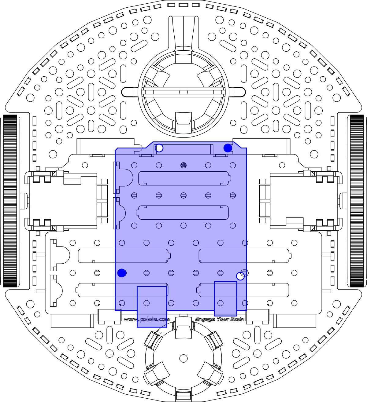
Also, I am not sure if you have seen it or not, but the “Dimensions and mounting holes” section of the Romi Chassis User’s Guide has a diagram that specifies what holes on the Romi Chassis align with the mounting holes on an Arduino Uno. The Arduino Mega has the same mounting holes (and a couple additional ones), so you should be able to mount it the same way if you wanted to. I have attached the diagram below for convenience.
By the way, do you plan on making more videos about your Romi robot? If so, do you have any applications or challenges in mind?
Brandon
Thanks for the info on the library and the alignment holes. I’ll look into that.
I do plan on doing more with this robot…for starters some (hopefully) funny and definitely pointless behaviors. I’m trying to do things other than object avoidance and line following.
I have an idea using the IMU chip to map a surface for a future project. I have your libraries for that chip.
I’ll try to share here and YouTube as I roll things out. I have no idea of a time table. I’m new to robotics. Some things that seem simple end up taking forever, and vice-versa.
That sounds great! We love seeing interesting ways our products are used. I look forward to seeing how your projects progress; good luck!
-Brandon
Here’s a link to the latest thing I did with the Romi. Light sensors and a buzzer and I stuck a foam head on it.
I put a link to the code in the in the description of the video. It’s nothing. . .turn left if the right sensor is higher, turn right if the left sensor is higher. Move forward otherwise. Turn around if its running away from the light. Stop when the light gets bright. I didn’t look at anyone else’s code before doing this – I assume some people are probably handling cases that I might be ignoring or have programmed ways to make the motion smoother.
I also put in a link to a pretty simple library I wrote for the drv8838. I found your library a little confusing. I’m not sure what it needed all of the static variables, and there was no constructor that allowed the user to set the pins. I also attached the sleep pins to mine. I like using those to shut it down when I’m testing things.
But, mine is not as general as yours, and I’m not experienced enough to understand what you were doing with the USE20Khz_PWM material. Mine does NOT handle that. Only used it on the mega2560 board, so I don’t think I need all that extra code.
-Mark
1 Like
Awesome! Thanks for sharing.
Our library uses timers to allow PWM signals to run at a 20 kHz frequency, which is above the audible range. However, as you noted, this limits its use to specific pins and our library does not support using the ATmega 2560 with this frequency (it is still compatible but uses analogWrite at 489 Hz and 1kHz PWM frequencies).
Brandon
1 Like