So I bought the full Romi Chassis partslist… chassis, motors, wheels, encoders, and the Motor Driver and Power Distribution Board for Romi Chassis. Assembled everything th the gude lists, added an A-Star 32U4 Prime SV microSD.
And realized that I have no clue what I do next to get the A-Star 32U4 to talk to the Romi board, as the Pololu Romi Chassis User’s Guide does not really talk about what connects to what…
So I just connect 3.5mm-pitch terminal blocks to the six motor driver output holes along the front edge of the board or someplace else since I installed the Romi Encoder Pair Kit? Am I using the double rown towards the middle instead? Does the A-Star just run the motors with the DRV8838 library?
Hello.
To start off, you will need to decide how you want to power the A-Star 32U4. If you want the entire robot (e.g. the motor driver and power distribution board and A-Star 32U4 Prime) to both be controlled with a single power switch, you can connect power from any of the VSW pins on the motor driver and power distribution board to the VIN pin on the A-Star 32U4, as well as a ground connection between the two boards. Please note that this will bypasses the reverse voltage protection on the A-Star 32U4 Prime.
As far as controlling the motors, the PWM, DIR, and SLP pins (for each motor) on the motor driver and power distribution board are available in the space between where the motors line up. If you do not need the SLP pins, you could use our DRV8835 Motor Shield Arduino library to control the motors. The additional connections you would need to make would be DIR and PWM for the left motor to pins 7 and 9 on the A-Star 32U4 Prime respectively, and DIR and PWM for the right motor to pins 8 and 10 on the A-Star 32U4 Prime.
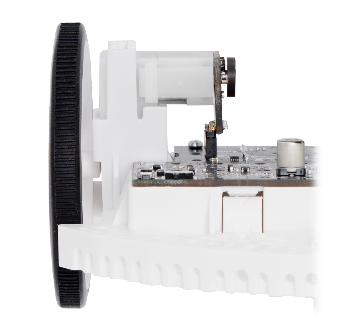
If you are using the Romi Encoders, the ML+, ML-, MR+, and MR- terminal block connections can be left disconnected; these are intended to be used for connecting the motor to the motor controller, but the Romi encoders handle this connection when plugged directly into the motor driver and power distribution board, as shown in this picture:
To access the encoder signals, you can make connections from the ELA, ELB, ERA, and ERB pins to the relevant pins on your A-Star 32U4 Prime (which pins are relevant will depend on your code). Please note that since the motors and encoders sit above these pins, there might not be room for headers, so you might consider soldering your wires directly to the pins. Alternatively, you might be able to solder a header in at an angle.
If you are unsure about any of the connections, you can post a proposed wiring diagram here, and I would be happy to take a look.
Brandon
Thank you, this is very helpful… I will respond when I have a purposed wiring diagram. Thanks again!
So this is interesting… wired it up as suggested and loaded the default example sketch (Examples => AStar32U4 => Motors).
Works fine for running the motors forward but when it hits the reverse subroutines it goes forward as well… does not seem to actually reverse.
I noticed, though, that you were talking about using the DRV8835 Motor Shield Arduino library to control the motors and I am using the AStar32U4 version… should I use the former instead?
e.g. should I use
#include <DRV8835MotorShield.h>
DRV8835MotorShield motors;
or
#include <AStar32U4.h>
AStar32U4Motors motors;
Disregard, answered my own question… I switched to DRV8835MotorShield for motor control, now works perfectly!
#include <AStar32U4.h>
#include <DRV8835MotorShield.h>
DRV8835MotorShield motors;
1 Like