I have the Romi kit for First.
I also purchased the Romi Arm kit.
I also have the Raspberry Pi+ installed
Raspberry Pi 3 Model B+ Board (3B+)
I see no instructions on where to connect the coonectors on the Romi 32U4 board.
These are the connectors coming from the Servo motors off the
Robot Arm Kit for Romi. And the green wire connector?
Thanks
David Powell
Question regarding the D24V22F6 for Romi.
Pololu 6V, 2.5A Step-Down Voltage Regulator D24V22F6
regulator.
Where exactly does this regulator fit on the 4022 32U4 board ?
Thanks
David
1 Like
Hello.
I combined your two threads since they were about very similar topics.
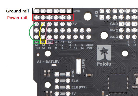
The Romi 32U4 Control Board has 8 free I/O pins, which can all be used to control servos. The most convenient way to do it would probably be to use pins A2, A3, and A4, since they are available on one of the expansion areas (in the corner of the board) that also has a power and ground bus you can use to power the servos.
The green wire on the servos is wire is optional and gives direct access to the servo’s position feedback potentiometer. If you want to use the feedback, you would need to connect it to a pin on the Romi 32U4 Control Board that is capable of reading analog signals, but it is not needed to use the servo normally.
You can find more details about the free pins available in the “Adding electronics” section of the Romi 32U4 Control Board user’s guide and information about the expansion areas in the “Expansion areas” section.
That power rail is not connected to anything by default, so you can connect your servo power to one of the unused pins on the rail to supply power to the servos. The regulator on the Romi 32U4 Control Board cannot handle enough current to drive all 3 servos while also powering the electronics and motors on the Romi Robot, so we generally recommend using a separate step-down regulator, such as the 6V, 2.5A Step-Down Voltage Regulator D24V22F6, if you want to power the servos from the 6xAA batteries on the Romi. To clarify, the regulator does not have a special spot to plug directly into the Romi 32U4 Control Board, but you can mount it to the chassis and use jumper wire to make the appropriate connections. The minimum connections required would be from VIN of the regulator to VSW on the Romi 32U4 Control Board, GND on the regulator to GND on the control board (you can use the ground bus discussed above), and VOUT on the regulator to the servo power pins (you can use the power bus discussed above).
Please note that if you want to control the servos from the Romi 32U4 Control Board using the Servo Arduino library, you will have to modify the library so it uses Timer3 instead of Timer1 (since the Romi libraries use Timer1 to generate the PWM signals for driving the motors). You can find details about doing this in the “Controlling a servo” section. Also, if you are using our “Raspberry Pi slave library for Arduino” to control the Romi from the Raspberry Pi, please note that the RomiRPiSlaveDemo.ino program does not have any special support for controlling servos, so you might consider modifying it to add that.
Brandon
Brandon,
I have the regulator ready to go.
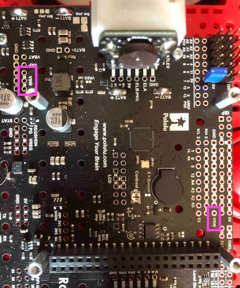
In the pic attached there are 2 places for the VSW ? Where exactly does the connection go to the the romi board…can you mark the board in the pic…
As you noted, VSW is available at multiple pins on the control board. It does not matter which one you use (they are all internally connected on the board).
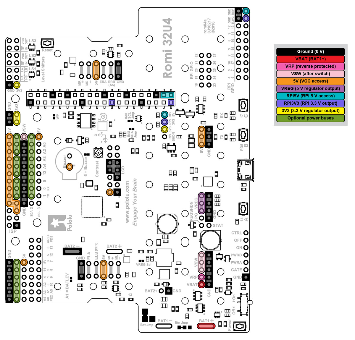
VSW is indicated on the following diagram (which comes from the “Expansion areas” section of the Romi 32U4 Control Board user’s guide) by the pink highlighting:
Brandon
Thank you very much !! Sir.
1 Like