
unsigned int position = robot.readLine(sensors, IR_EMITTERS_ON);
Dear All please help me understand code sample for above
I mean code for used measure sensor output in single umerical result
unsigned int position = robot.readLine(sensors, IR_EMITTERS_ON);
Dear All please help me understand code sample for above
I mean code for used measure sensor output in single umerical result
Hello.
It is not entirely clear to me what specific product you are referring to (i.e. where that code came from) or what exactly you are asking, but it sounds like you want to know how the readLine() function takes all of the line sensor readings and outputs a single value.
You can find details about that in the documentation for the readLineBlack() function in our Arduino library for our QTR reflectance sensors. (Please note that our updated QTR library separates the readLine() function into two: one for a black line and one for a white line). Essentially, it just takes a weighted average of the sensor indices. If you want to see the code for it, you can look through the readLinePrivate() function defined on line 644 in QTRSensors.cpp.
Brandon
Hello BrandonM
Sorry for less explain
We have old 3pi robot and old 8QTRC sensor
we are teaching robotics for children using them and Arduino code
Our students are asking about how to take single value using code
https://pololu.github.io/qtr-sensors-arduino/_q_t_r_sensors_8cpp_source.html
I tired to understand the codes in the above library how to extract specific code for read the single value but I can not understand it as lot of codes are there which is can not understand
Can you please give us specific code sample for the teaching purpose
 switch (_type)
   {
     case QTRType::RC:
       for (uint8_t i = start; i < _sensorCount; i += step)
       {
         sensorValues[i] = _maxValue;
         // make sensor line an output (drives low briefly, but doesn't matter)
         pinMode(_sensorPins[i], OUTPUT);
         // drive sensor line high
         digitalWrite(_sensorPins[i], HIGH);
       }

       delayMicroseconds(10); // charge lines for 10 us

       {
         // disable interrupts so we can switch all the pins as close to the same
         // time as possible
         noInterrupts();

         // record start time before the first sensor is switched to input
         // (similarly, time is checked before the first sensor is read in the
         // loop below)
         uint32_t startTime = micros();
         uint16_t time = 0;

         for (uint8_t i = start; i < _sensorCount; i += step)
         {
           // make sensor line an input (should also ensure pull-up is disabled)
           pinMode(_sensorPins[i], INPUT);
         }

         interrupts(); // re-enable

         while (time < _maxValue)
         {
           // disable interrupts so we can read all the pins as close to the same
           // time as possible
           noInterrupts();

           time = micros() - startTime;
           for (uint8_t i = start; i < _sensorCount; i += step)
           {
             if ((digitalRead(_sensorPins[i]) == LOW) && (time < sensorValues[i]))
             {
               // record the first time the line reads low
               sensorValues[i] = time;
             }
           }

           interrupts(); // re-enable
         }
       }
       return;
No idea about duty of _maxValue in the above code
Can you please explain operation of below codes it is grate thanks
 time = micros() - startTime;
           for (uint8_t i = start; i < _sensorCount; i += step)
           {
             if ((digitalRead(_sensorPins[i]) == LOW) && (time < sensorValues[i]))
             {
               // record the first time the line reads low
               sensorValues[i] = time;
             }
           }
Thanks in advanced
Thanks again
Hello.
Unfortunately, I am still not entirely sure what you are asking. It sounds like you might be asking how to look at the individual sensor readings after calling one of the readLine() functions. If that’s the case, you can access them from the array passed to the readLine() function as the first argument. For example, if you use the line of code you posted about in your original question (i.e. unsigned int position = robot.readLine(sensors, IR_EMITTERS_ON);) the individual sensor readings will be stored in the sensors array (i.e. sensors[0] will hold the reading for sensor 0 and so on).
This specific snippet of code you asked about is how the RC sensors take their readings:
time = micros() - startTime;
           for (uint8_t i = start; i < _sensorCount; i += step)
           {
             if ((digitalRead(_sensorPins[i]) == LOW) && (time < sensorValues[i]))
             {
               // record the first time the line reads low
               sensorValues[i] = time;
             }
           }
Before this code is called, capacitors on the output node are charged by driving the line high and that snipped of code is timing how long it takes the output voltage for each sensor to decay. The brighter the reflectance, the faster the voltage will decay.
Brandon
Thanks for reply ad advise
Can you please explain the operation of following code
if ((digitalRead(_sensorPins[i]) == LOW) && (time < sensorValues[i]))
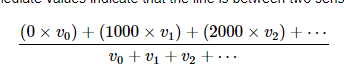
and also please provide the code sniper for the following calcutation
Thanks in advanced
The comment in the related block from Brandon’s post pretty much sums it up.
The capacitor is charged and the code is then timing how long it takes to discharge. When it is discharged it will read as LOW so this code stores away the time that it first sees the sensor read as low. The time < sensorValues[i]) part of the conditional makes sure that sensorValues[i] is only updated the one time since once it reads LOW, it will continue to read as LOW.
You can see the sums found in the divisor and dividend of the above equation in the code here:
I hope that helps.