
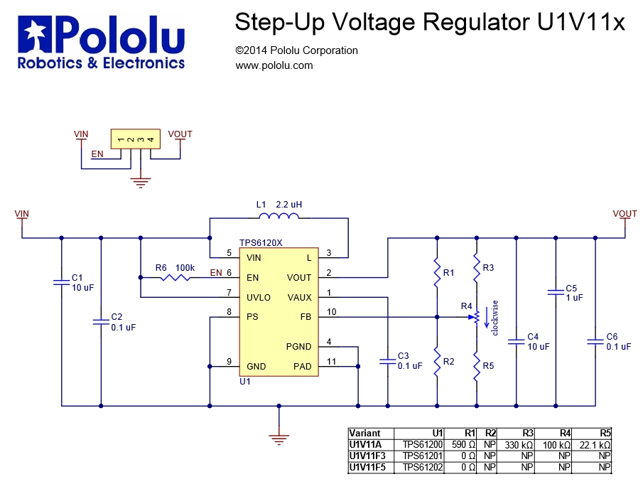
Is the resistance of resistor R1 = 390 Ohm indicated correctly in the diagram (see below)?
Hello RomanS.
The schematic in your post shows R1 = 590Ω, but this was actually a typo; R1 is 590kΩ. We have fixed it in our documentation.
Thank you for bringing it to our attention!
Brandon
Thanks for the reply. A few more questions. What is the purpose of resistor R1 = 590 kOhm (the device will work fine without it)? Why is there space left on the PCB for resistor R2, even though it’s listed as NP (not place) in the text?
Hello.
R1 and R2 are designed to allow us to have finer control over how the potentiometer affects the voltage to the FB pin (which is used to set the output voltage). As you can see in the diagram, R1 is in parallel with R3 + the high side of the potentiometer, and creates a voltage divider with R5 + the low side of the potentiometer. Removing R1 would change how the potentiometer maps to the output voltage. I do not recommend removing it.
Can you explain what you are trying to do?
Brandon
Thanks for the explanation. If R1=590 kOhm is set, then the output voltage changes 1.36…5.25 V. If you remove resistor R1, then the output voltage changes 1.85…5.25 V. This is calculated using the formula from the TPS6120x datasheet. You do not recommend removing resistor R1, but the technical data of U1B11A indicates a range of 2…5.25 V. This is done both when resistor R1 is present and when resistor R1 is absent.
Can you explain what you are trying to do?
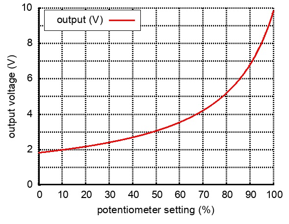
The value of R1 controls the shape and also the maximum range of the output voltage curve shown in this graph on the regulator’s product page. Without R1, the curve gets steeper, making it harder to set the precise output voltage you want and allowing it to reach high enough voltages to damage the chip.
For reference, here’s a graph of the calculations with R1 removed:
Brandon