This is a really slick design. I needed to remap the pins to avoid using the analog inputs. I cut the traces similar to how I have with strip boards; using a small drill bit and drill press.
My concern is if this is a multi-layer board such that I may have inadvertently cut a trace that may run under trace on the top layer? I suspect not given the proximity of the vias.
When powering up the board the Red LEDs no longer light and I have looked at the IR LEDs through two different cameras - seeing no IR light.
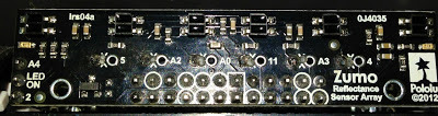
The enable terminal is in place, however the jumper is removed. The Red LEDs were functioning prior to my cutting the traces for remapping. In the picture I have soldered a resister on the IO line for each sensor.
Any ideas ~ Thanks!
The LEDON MOSFET is the culprit.
I have verified traces using a DMM based on the schematic and determined that the problem is with the mosfet. While by-passing (connecting the LED series gnd directly to gnd across what would be R9) the mosfet the LEDs are activated as expected. IR LEDs confirmed using camera trick.
I reseeded the mosfet, no change. Perhaps the mosfet was damaged while either cutting the traces or soldering in new resisters on the IO pins on the reverse side. This would be unexpected.
Alternatively perhaps an ESD event occurred across the device 
Did the sensor array work as expected before remapping the outputs?
The Zumo reflectance sensor array is a 2-layer board, and the traces you drilled out are far from the traces that are involved in the MOSFET circuit… It is unlikely that drilling was directly responsible, but it is suspicious that it stopped working right afterward. Could you try connecting the LED ON pin directly to VCC? This will help eliminate the pull-up resistor as the culprit.
By the way, cutting those traces with a drill seems dangerous. I recommend using a sharp utility knife or box cutter to cut those traces, instead.
- Jeremy
Hi Jeremy -
Agreed, hind sight on drilling = not ideal. If I were to do this over, would go the utility knife route. I did try a sharp screw driver first. The funny thing is I opted for the drill because I felt I had better control. I was concerned about slipping with the blade and cutting or damaging another part of the board.
After all of this troubleshooting I now see hidden VIAs that give more clues to the 2nd layer. That black paint that makes it look so clean hides all that detail.
As you suggested I hooked the LEDON pin to VCC and yes it activated. This is surprising because I would have expected hooking LEDON to the 5v pin would have done this as well given that is what would come from the Arduino. So the extra voltage of VCC vs 5v is enough to trip the gate? The in circuit resistance across R10 (47K) = 46.8K. I checked the trace between 5V and R10 (coming off caps C6 or C3) all the way back to the 5V on the header.
Thanks for your troubleshooting assistance ~ I now understand how this board is design in a lot more detail than I would of otherwise… Always a bright side to issues, usually leads to learning something!
I do not know why connecting LEDON to the 5V pin did not work. I expect the VCC pin to measure 5V, and there should not be a difference between the 5V pin and the VCC pin.
It sounds like the pull up resistor is no longer driving the MOSFET gate HIGH. As long as you drive the LEDON pin HIGH, you should be able to use the sensor array.
- Jeremy
I am using the Reflectance sensor connected to the Zumo Shield. The Shield has a DC-DC converter that drives the battery voltage up to VCC and also regulates the 5V. This is why VCC has higher than 5V.
What I am finding is that the pull up resister is providing +voltage to the MOSFET, however the MOSFET no longer responds to a voltage of 5V or less. Even with the pullup resister shorted the MOSFET doesn’t activate.
I have found a work around based on the schematic, so the device is usable; jumper R9 - the board is already setup for this as a MOSFET by-pass.
However I would like to better understand what happened if you have any more thoughts, or perhaps it will remain a mystery.
BTW - I already ordered another sensor, should be here Monday. I will compare the working vs non-working for additional clues…
An on-board boost regulator generates 7.45 V to power the Arduino through its Vin pin. Vin is not the same as VCC. VCC usually refers to logic voltage (usually 3.3 V or 5 V), and in the case of the shield, VCC is supplied by the Arduino’s 5V regulator. Applying 7.45 V to the MOSFET might have caused it to break, and I do not recommend connecting Vin to LEDON.
- Jeremy
