
Hello everyone:
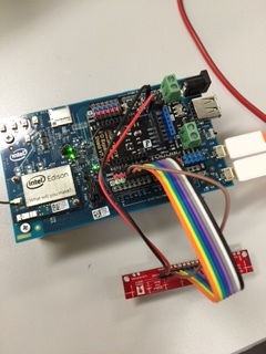
I have a QTR 8RC Reflectanse sensor and intel edision. I am not able to get right reading from the sensor. I followed the online instruction while wiring the cable. I believe the sensor works all right.

However, readings from the sensor are bit strange. No matter how I change the background, white, grey or black, all the RC sensors give the following values:
6 6 6 6 6 6 6 6
5 5 5 5 5 5 5 5
5 5 5 5 5 5 5 5
5 5 5 5 5 5 5 5
6 6 6 6 6 6 6 6
5 5 5 5 5 5 5 5
5 5 5 5 5 5 5 5
The code I am using is based on the examples provided in the arduino library folder.
#include <QTRSensors.h>

// This example is designed for use with eight QTR-1RC sensors or the eight sensors of a
// QTR-8RC module.  These reflectance sensors should be connected to digital inputs 3 to 10.
// The QTR-8RC's emitter control pin (LEDON) can optionally be connected to digital pin 2,
// or you can leave it disconnected and change the EMITTER_PIN #define below from 2 to
// QTR_NO_EMITTER_PIN.

// The main loop of the example reads the raw sensor values (uncalibrated).
// You can test this by taping a piece of 3/4" black electrical tape to a piece of white
// paper and sliding the sensor across it.  It prints the sensor values to the serial
// monitor as numbers from 0 (maximum reflectance) to 2500 (minimum reflectance).


#define NUM_SENSORS   8   // number of sensors used
#define TIMEOUT       2500  // waits for 2500 microseconds for sensor outputs to go low
#define EMITTER_PIN   2     // emitter is controlled by digital pin 2

// sensors 0 through 7 are connected to digital pins 3 through 10, respectively
QTRSensorsRC qtrrc((unsigned char[]) {3,4,5,6,7,8,9,10},
  NUM_SENSORS, TIMEOUT, EMITTER_PIN);
unsigned int sensorValues[NUM_SENSORS];


void setup()
{
  delay(500);
  digitalWrite(EMITTER_PIN, HIGH);    // turn on Arduino's LED to indicate we are in calibration mode

  Serial.begin(9600); // set the data rate in bits per second for serial data transmission
  delay(1000);
}


void loop()
{
  // read raw sensor values
  qtrrc.read(sensorValues);

  // print the sensor values as numbers from 0 to 2500, where 0 means maximum reflectance and
  // 1023 means minimum reflectance
  for (unsigned char i = 0; i < NUM_SENSORS; i++)
  {
    Serial.print(sensorValues[i]);
    Serial.print('\t'); // tab to format the raw data into columns in the Serial monitor
  }
  Serial.println();

  delay(250);
}
While, if I only read a single RC sensor, for example, I change the following
#define NUM_SENSORS 1
QTRSensorsRC qtrrc((unsigned char[]) {3}, NUM_SENSORS, TIMEOUT, EMITTER_PIN);
Readings are:
2500
728
5
5
4
5
6
109
203
45
228
299
298
167
338
262
Can anyone help me with this problem ?
Also, I am bit confused about the comments:
// print the sensor values as numbers from 0 to 2500, where 0 means maximum reflectance and
// 1023 means minimum reflectance
if 1023 is the minimum, why I get 2500 ?
Thanks in advance.
Josh