Hi!
That’s a Wonderful page, congratulations! 
i have a little question for you, i have seen this video:
I have an rc car, i would use your rc switch to simulate corner lights with fog lights like in real car, the same of this video:
what should i do? is it possible to order a specific switch to solve my problem?
it’s a cool detail that i have never seen before on rc car!

I look forward to your answer,
Best regards,
Angel
Hello, Angel.
I moved your post the to “Other Pololu products” section of our support forum since it seems more appropriate.
You should be able to do that using a pair of our RC switches (one for each side). In particular, you might consider the RC switch with small low-side MOSFET. If you connect the signal to both RC switches you can then configure the threshold values on them so one triggers when turning right and one triggers when turning left.
To configure the RC switches, you would first need to put the RC switch in learning mode, as described in the “Configuring Your RC Switch” section of the RC switch user’s guide. Then you can follow the steps in the “General Configuration Procedure” section. Note that one of the switches will probably need to have inversion enabled so it is active when the signal is below the threshold instead of above.
Brandon
Thank you so much Brandom, i understand
hi brandom,so sorry for disturbing, i would add a little detail at my corner light with fog light, in particular fading out led light like in real cars, is it possible ? what should i do before making my order?
The RC switch would not be able to actively fade out the LED like that on its own. You might be able to get a fading effect by adding some capacitors, but if you need active control of the LEDs, you might be better off processing the signals with a separate microcontroller like an Arduino and writing your own program that controls the LEDs like you want.
Brandon
okok thank you so much, I think that using a capacitor is enough, Is it possible to see how this capacitor is connected to the circuit plase? Where i can find a simple wiring? So sorry for disturbing
With a quick Internet search I found this article on the Learning about Electronics website that looks like it might be a good reference for what you are doing. The video on that page includes a demonstration using a few different capacitors to show how it affects the LED.
Brandon
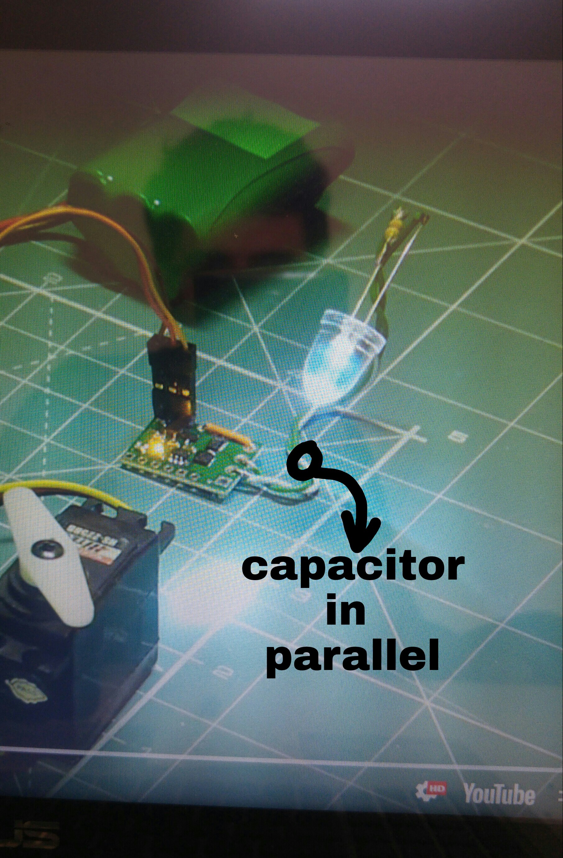
Wonderful! That’s exactly what I was looking for. If i understand correctly, i could connect a capacitor in parallel like in the photo below to solve my problem, is it right? 
I cannot tell exactly where you are indicating to add the capacitor in your picture, but the way you described it sounds correct. It should be in parallel with your LED and series resistor as shown in the diagram on that “Learning about Electronics” web page I linked to in my previous post.
Brandon
Yes, exactly, thank you for your time
Best regards,
Angelo