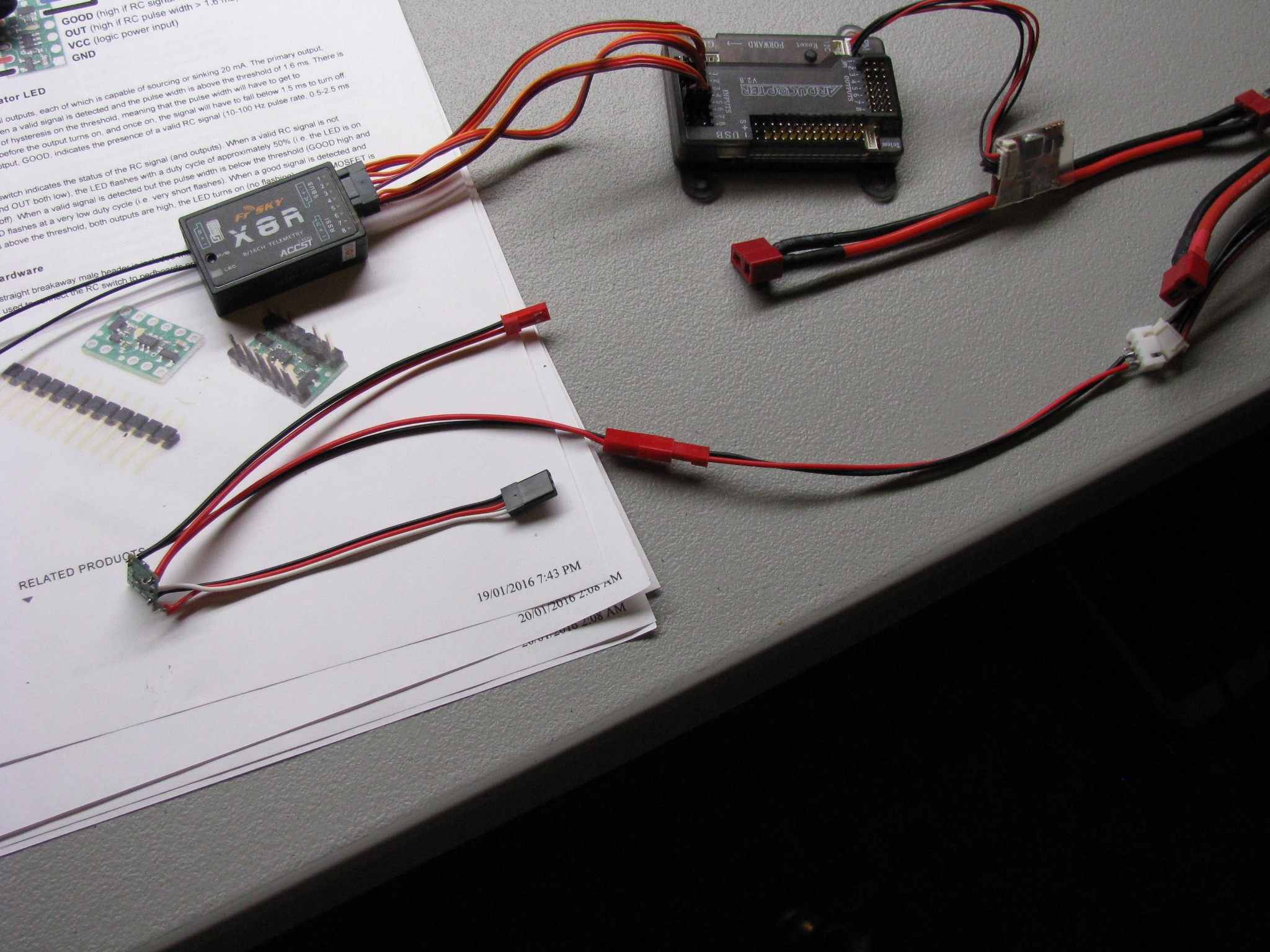
Hi, Could someone please help. I must be missing something, obvious connected wrong. Thought connected as all drawings show for rc control. Connected white, red, black to rc in, vrc, and gnd respectively. Connected pads on bottom back so VCC =VRC to power board. Soldered leads to top left + and right - for load. Soldered leads to next set down same for load supply power.
Connected servo lead to receiver, nothing attached to load leads power or load.
Turned on, tested with transmitter, working ok, led flash with switch off, led solid when switch on. Seems ok.
Connected power to load end. Applied ~4.2 V, one lead off balance charge port off 3S 11.1V lipo battery. (same battery supplying power module, apm and receiver) (hopefully can follow in pic attached)
And oooops, problem.
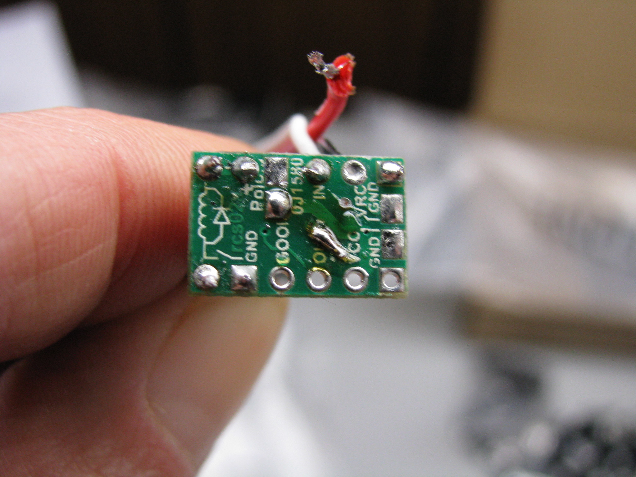
Hopefully can see in pic, burned trace on back of board. Not sure why??? Dead short or something, obviously missing something.
Solder trace to repair.
Reconnect, without load power supplied, appears to still be ok, still switches with receiver (at least appears ok by red led).
Wasn’t sure what to try next, so removed red lead from vrc, desoldered vcc and vrc pads.
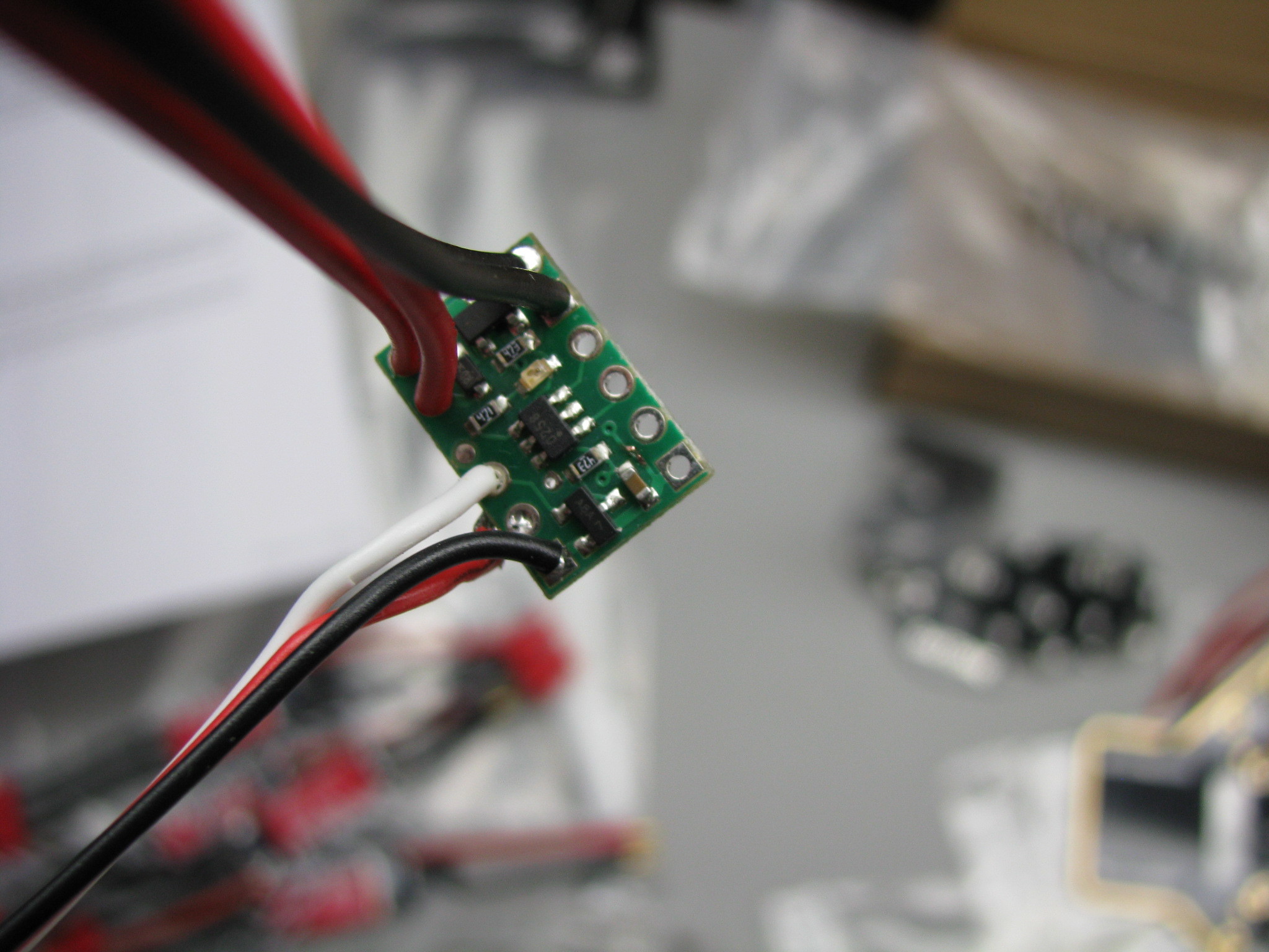
Connected servo lead to receiver, obviously led not working since power not supplied to board. Thought maybe I misunderstood and board would get power from load power supply (even though pads were never soldered together on back). Connected power to load leads again (4.2v off balance lead) and AGAIN off goes trace on front of board.
I must be missing something, am I dead shorting something, creating a ground loop or something.
Any help greatly appreciated.
Thank you for including pictures. I cannot tell how your battery is connected, but from your description of the problem, it sounds like you might be connecting it backwards, and causing a short. Can you check the polarity of the wires with a multimeter to make sure you are connecting it properly?
Also, please note that tapping into the individual cells in a LiPo battery pack can cause the cells to drain unevenly, so it is generally not good practice to do so.
By the way, it looks like you have the older version of the RC Switch with Small Low-Side MOSFET, so you should make sure you are referencing the RC Switch with Small Low-Side MOSFET (rcs02a) product page.
Thanks for response Brandon,
I knew it would be something kind of simple, mistake made while in hurry to test.
As you mentioned, I know not good idea to pull from 1 cell, this was just for testing, and ultimately was the mistake.
Polarity was correct. Was testing, took load power from balance lead of 3S battery, from red + and #1 balance lead black -, at had 4.2 V.
Not realizing power module supplying apm, receiver and switch, somehow uses negative which is equivalent to black balance lead #3
to send out for power to system. So when connected load voltage, had potential between negatives! (2x 4.2) 8.4 volts! From between #3 balance lead and balance lead #1, from across 2 cells in series of 3 of the 3S battery!!! (really stupid mistake after I think about it!!!)
All the balance leads being black, and being in a hurry, messed up thought process. They really should be different colours, since they are
really center taps on a multi voltage power supply!
Thanks for getting my thought process going.
Soldered trace back, everythings working properly.
Thanks
Dave
One quick further question if someone could help.
Rc switches all working good from Rx. Now tried using one on side digital output pins of APM and doesn’t
seem to work. Am I correct this is because Rx puts out PWM signal while Apm digitals are just on or off?
(APM outputs work on a small single LED card)
Is there a way, and can these switches be used on a digital output?
(wanting to drive led strips larger than apm can handle directly)
Thanks
BrandonM, Your reply to davfar may also be related to a problem I’m having regarding a relay I’m trying to use on my Quad. I just posted on here requesting help. I was reading some of these posts and the tail end of this conversation I think may be linked to my solution.
I’m trying to control relay 2485 from a receiver channel. I don’t have any problem wiring LED and 3s lipo battery that I’m using to power LED’s. I can verify that wiring to NC will keep the light on and wiring to NO will have the light off until relay activated. problem is that I can’t seem to activate the relay from the output of receiver. I thought these relays worked with RC radios and signals. Exact path is Futaba 12 channel data merged onto SPPM stream, transmitted to ImmersionRC receiver that takes channels 1-5 and forwards them still in SPPM (out on ch 1 of servo receiver) to Vector Flight controller. The other 6-12 channels are converted back and output on servo outputs of receiver on channels 2 through 8. I have two of these channels going to relay. Do you know if this type of setup should work?
Any help appreciated!!