I often successfully used your “RC Switch with digital output # 2801” in different projects. No problem when it does not share its control signal (RC IN) with other circuits.
But here I am having a problem when this signal is shared with a microcontroller.
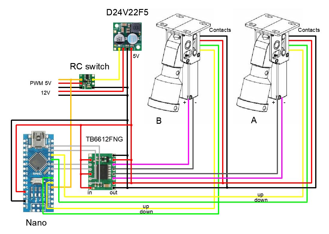
My goal is actually to control a DIY drone landing gear, made from ARRIS X3 mechanics but whose original components (burnt out) have been replaced. So I use 2 Pololu HPCB 12V micro-motors, Pololu TB6612FNG motor driver and I added 4 optical limit switches, to prevent the motors from jamming.
The driver inputs are calculated by an Arduino Nano which decodes the PWM control signal transmitted by the radio :
1ms => cut system power (OFF)
1.5ms => raise the gears (UP)
2ms => lower the gears (DOWN )
The whole system (motors, controller, optical switches, Arduino Nano) is supplied with 5V. This voltage is produced by a 5V Pololu D24V22F5 regulator, connected to the general 12V power supply of the drone. It is therefore possible to cut the power supply to the system by setting the EN input of the regulator to the LOW level.
For this, the PWM control signal is also sent to an RC Switch with digital output # 2801, whose threshold has been set at 1.25ms and whose output OUT is connected to the EN input of the regulator. Thus the OFF command will cut off the 5V power supply to the other components.
The problem is that the RC switch goes into Safe Start Mode (2 short flashes /s) when the commands UP or DOWN are sent, probably because of the disturbance created on the PWM line when the Arduino Nano is powered up at 5V. I found a solution which consists of returning for a short time to the OFF state, then returning to the desired state (UP-OFF-UP or DOWN-OFF-DOWN). This problem can also been solved using 2 PWM signals: one to activate the regulator and another to select UP or DOWN.
But do you have a solution to avoid this switch to Safe Start Mode, by sending only UP or DOWN and using only one PWM control signal ?
I just found the problem : the RC switch was powered in 5V by the line coming from the RX (VCC=VRC here), but the command PWM signal has a 3,3V logic. It’s a characteristic of my RX which is an Frsky X8R : all the channels have this 3.3V logic level, even when the RX is 5V powered.
In this situation, the RC switch does’nt recognize a 1ms PWM signal and the led blinks with a 50% duty cycle (state 1), but OUT is LOW, which is requested. Unfortunately, when the PWM command is set over the switch threshold (UP or DOWN), it goes into the safe start mode, as precised in the user’s guide.
Hence, a good solution consists in reducing the VCR input to from 5V to 3.3V : a very small regulator or even a resistance bridge can do the job because the intensity is very small (< 5mA).
With this little modification, the RC switch run perfectly and its functionnality is usefull : for instance, with a 9V alimentation, I measure 0.3mA when the regulator is disabled (EN=LOW), and 70mA (motors off) to 150mA (motor on) when enabled.
Hi Claire,
I would like to present here another example of a Pololu RC Switch with Digital Output, with a problem of Safe Start Mode… And a solution to solve it.
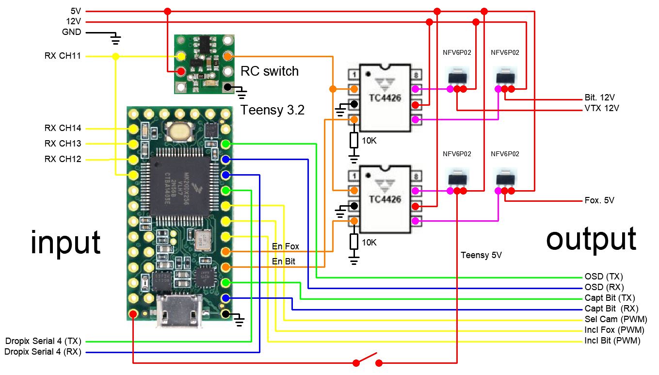
The scheme below corresponds to a video controller, in a DIY drone. Here the scope is to drive a video system composed with 2 directable cameras, a VTX (Video Transmitter) with a programmable OSD (On Screen Display) and a microcontroller (Teensy 3.2) to decode the commands from the radio (4 PWM channels, with 3.3V logic level) : select a camera, power it, tilt it, capture a video, take a photo and add specific texts on the OSD.
An unique channel (CH11) is used to select the camera and to switch On/Off the system. So this PWM signal is treated also by a Pololu RC switch with a digital output driving 2 high-side Mosfets (NFV6P02) and their drivers (TC4426), to power On/Off the Teensy (5V) and the VTX (12V). 2 other high-side Mosfets are driven by the Teensy to power the selected camera.
When this PWM CH11 signal goes over the RC switch threshold, the switch enters in the Safe Start Mode.
I tried to add a polarized capacity, between RC IN and GND, as mentionned in the manual, but without any success.
The problem disappers if the Teensy powering is not driven by the RC switch and for example permanently powered. But, this is not a good solution, because this induces unnecessary current consumtion when the video system is off.
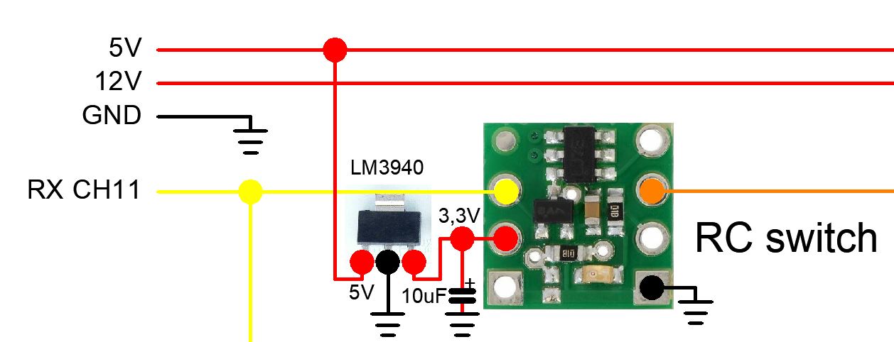
So I finally opted to add a 3.3V regulator (TI LM3940) with a tantale 10uF polarized condensator on its output pin and this solves the problem : no Safe Start Mode when CH11 signal goes over the threshold !
Best regards.
Thanks for posting about your new issue and solution! Since adding a regulator fixed the issue, it seems like there might be something unusual going on with your 5V line, such as transients that are affecting the RC switch. If you want to look into it further, I recommend looking at that line with an oscilloscope when you turn the Teensy on and off.
Thank’s Claire for your rapid response.
I looked to the 5V level with an oscilloscope : no visible perturbation and I don’t really understand why the RC Switch is going into the Safe Start Mode.
After some unsuccessfull experiments (add a 1uF capacity, add a N-Mosfet to isolate CH11 from the Teensy), I just observed that the 3.3V regulator solves this mysterious (for me !) problem.
I haven’t tested other switches (like the one with a low-side Mosfet) because here my problem is to use high-side Mosfets.
Best regards.
Jac