I am unsure how you intend on measuring the motor speed through one of the motor leads. What kind of motor are you using? Could you provide a link to its specifications? What are you using to supply your motor with the PWM signal?
A normal RC motor has three wires. The speed controller alternates a pwm signal on these three wires. So each wire has a pwm-ground-ground-pwm-ground-ground-etc cycle.
The time between rising and falling edge divided by the time between two rising edges delivers the throttle percentage. I know my throttle-IN signal but not what the speed controller does with that input, I am interested in real throttle out.
The time beween two pwm blocks has a relation to motor rpm depending on the number of poles of the motor.
If I can recognise the motor pwm signal and use an interrupt I can determine both throttle and rpm.
All I need is a 5V pwm input signal coming from a 14.4V motor pwm.
One solution is to use a zener diode and resistor but I thought this level shifter might work too.
I am not sure how well measuring a lead on a BLDC motor would work with the our level shifter. I expect there to be large variations and spikes in the voltage that might make it hard to measure the signal without some kind of filter. Using a Zener diode like you suggested might work. However, since you are trying to determine RPM of your motor, it will probably be easier to use the Kv rating of the BLDC motor along with its current draw instead.
Using a Hall sensor for rpm or Amp sensor for load works, the idea of taking one of the motor leads makes installation less complex but will challenge my programming skills.
I will start with a 4.7V zener with a 390 Ohm resistor (aiming for 25 mA) and use the SLO scope to see what signal we have to work with.
Here is the design:
We use timer1 (TCNT1) for measuring the moment of a rising or falling edge
During pwm measurement we calculate the percentage when rising edge appears fast enough after the last one, at a long pause the input is for rpm calculation.
Timer1 counts to 50.000 at 50Hz (mode 14 pwm with prescaler 8 on Baby-O)
Timer1 counts to 250 at 10kHz for pwm input (8 to 10 kHz)
Timer1 counts to max 2142 for rpm input (14 pole, 7 commutations per rev, max 10.000 rpm)
At timer1 overflow
valid =0; // next calculation is invalid for percentage, next calculation is rpm input[/code]

At rising edge
[code]rise = TCNT1; // collect moment
if (valid == 1) // 2nd or later passage after overflow timer1
{
	if ((rise – lastrise)<=500) // short enough after last pulse = pwm
	{
                percentage = (((lastfall – lastrise)*100)/(rise-lastrise)); // calculate
        }
	else
        {
                rpmrise = rise; // first rise after long period without timer1 overflow;
                rpminput = (rpmrise – lastrpmrise); // calculate counts between commutations
                lastrpmrise = rpmrise; // remember last first rise
        }
}
else
{
        valid = 1; // only once per timer1 overflow
        lastrpmrise = rise; // firstrise after timer1 overflow
}

lastrise = rise;// store last rise
At falling edge
All there is left is to build a prototype and see if this is true
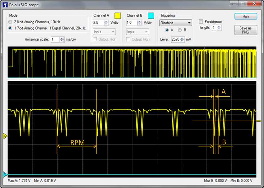
I tried to measure the motor pulses with a SLO Scope, the power cycle is visible although the 20 kHz of the SLO Scope is too slow to measure the 10 kHz PWM. Surprisingly the output is high and gnd during powered cycle. You can clearly see the 1/3 power and 2/3 waiting period. I expect the pulses to be better than shown on the scope and will give it a try to write some logic for rpm measurements.
It is neat that you are able to see the motor pulses and measure RPM from it. It is unclear from the screenshot, but it looks like there are voltage spikes that are going below ground (0V). If this is the case, I recommend not using the AVR programmer to measure the pulses since it can get damaged.
There are no negative spikes shown on the SLO Scope screen; however, that does not mean there are not negative voltages on the line you are measuring. If there are spikes that are going below 0V, they would be truncated in the program since it can only measure between 0V and VCC. I suggest you measure the line with an actual oscilloscope to make sure there are not any negative spikes. If there are, using the AVR programmer to measure the voltage is not advised.
95% of the time I get a proper reading when counting the time passed on both pwm percentage and rpm. This seems to stabilize at higher rpm.
I have no access to a proper scope to see what really happens. Without that information I could end up damaging the input port om my Baby-O.
EagleTree makes a RPM sensor for use of their data loggers. I assume that if it fits a logger it can do no harm to my processor too. This seems to be a product ready for use, I just ordered one and will see what happens.
I ordered an EagleTree rpm sensor and attached it to my motor.
It took a while to figure out that the RED wire needs to be attached to GND and the BLACK wire to 5Volts before I got a reading. For comparison I attached a Hall sensor with two magnets to the other input.
With my 14 pole motor I get nicely 7 pulses per two hall pasages which is excellent for measuring rpm. Sadly the harware filtering does not allow to extract the pwm percentage.