
like me!
High Guys,
First I checked on the serial servo controller. Once I stepped behind, i moved on the RC receiver input. This should help the newbe like I am, with a code written in plain, understandable matter. This should be the start for doing better.
There are two different types of receivers:
- The servos are controlled in seriell internally, albeit they are presented from CH1- CH… (looks like parallel)
- The servo output is parallel (needs different approach to get in)
This code is written for the serial sum RXes. Good news, you don´t need to open the receiver!
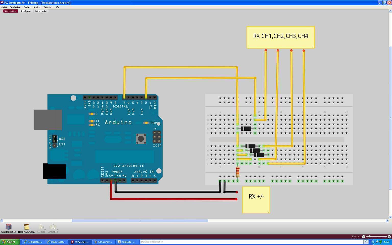
Hardware
diodes (amount equals to channels connected to the arduino)
1x 22k resistor
You may do it with an “OR” chip 74LS32N as well. Looks good, but result is the same as the antique diode technic.
1x RC receiver where signals are presented in serial format (sum) to the servos. this are mainly older and/or simpler Rx.
1x Arduino
Description:
Only 2 digital pins are used for how many channels you like (8 max, due to timing). In my example Pin 2 is Puls detect for CH1 (must be CH1). Pin 7 is used for the by diodes now combined again sum signal from CH1 to …
These pins are connected to the signal line of the RX output.
Signal length varies from 1ms to about 2 ms, center is 1.5 ms per channels. Every 22 ms the cycle starts again.
So a 4 CH sumsignal input varies from a minmum of 4 ms to 8 ms within in the 22ms time frame. The rest may be filled up, with the computer doing some useful calcs in its own loop. If you need more computing time it should be no problem, as if one input is missed, the rate is only halfed (still at about 20 times per second) but allows at least 35 ms x20/sec of other things to do.
Furtunately each channel shifts the following one in time, so that serial detection on one pin is even with pulsin possible.
Due to the detect of “High” it may never jump into the wrong pulses.
No timer or interrupt are used!
If you are going to implement your calcs for the servos please do it where the print commands start.
The accuracy is good enough and if you use one of the Pololu servo boards, there is absolutely no jitter to be seen on the servoarms.
Code:
All code is documented. Please feel tfree to experiment!
//Channel 1 = analogpin2
//Channelsum(1234)=analogpin7

byte Rx1 = 2; // pin Receiver CH1
byte Rxin = 7; //pin Reiceiver CH 1234
byte puls= HIGH; //puls Rx CH1
int Rxon= 0; // RX Failsafe
int PPM1 = 0; //Length signal CH1
int PPM2 = 0; //Length signal CH2
int PPM3 = 0; //Length signal CH3
int PPM4 = 0; //Length signal CH4
int NOP = 0;   //Pulse detect
#define shift1 54 // Time shift center CH1
#define shift2 -160 // Time shift center CH2
#define shift3 15 // Time shift center CH3
#define shift4 20 // Time shift center CH4

void setup()
{
  pinMode(Rx1,INPUT); //set pin as input
  pinMode(Rxin,INPUT); //set pin as input
  Serial.begin(57600); // set up Serial at 57600 bps
}

void loop() {

 puls=digitalRead(Rx1); //read level of Rx1
if (puls==LOW) { //if level is low, read all PPM)
    PPM1=pulseIn(Rxin,HIGH); // read PPM CH1
    PPM2=pulseIn(Rxin,HIGH); // read PPM CH2
    PPM3=pulseIn(Rxin,HIGH); // read PPM CH3
    PPM4=pulseIn(Rxin,HIGH); // read PPM CH4
    puls=HIGH; //set variable CH1 detect
    NOP=PPM1;
}
if (NOP==0) { // Failsafe /no PPM detect
    PPM1=3000; // set value CH1
    PPM2=2000; // set value CH2 Motor
    PPM3=3000; // set value CH3
    PPM4=3000; // set value CH4
}
 else {                       //double PPM and adjust
   PPM1=(PPM1+PPM1+shift1);
   PPM2=(PPM2+PPM2+shift2);
   PPM3=(PPM3+PPM3+shift4);
   PPM4=(PPM4+PPM4+shift4);
   }
Serial.print(" CH Seite= ");
Serial.print(PPM1);
Serial.print(" CH Motor= ");
Serial.print(PPM2);
Serial.print(" CH Quer= ");
Serial.print(PPM3);
Serial.print(" CH Hoch= ");
Serial.println(PPM4);
}
b.r.
Wolfgang

