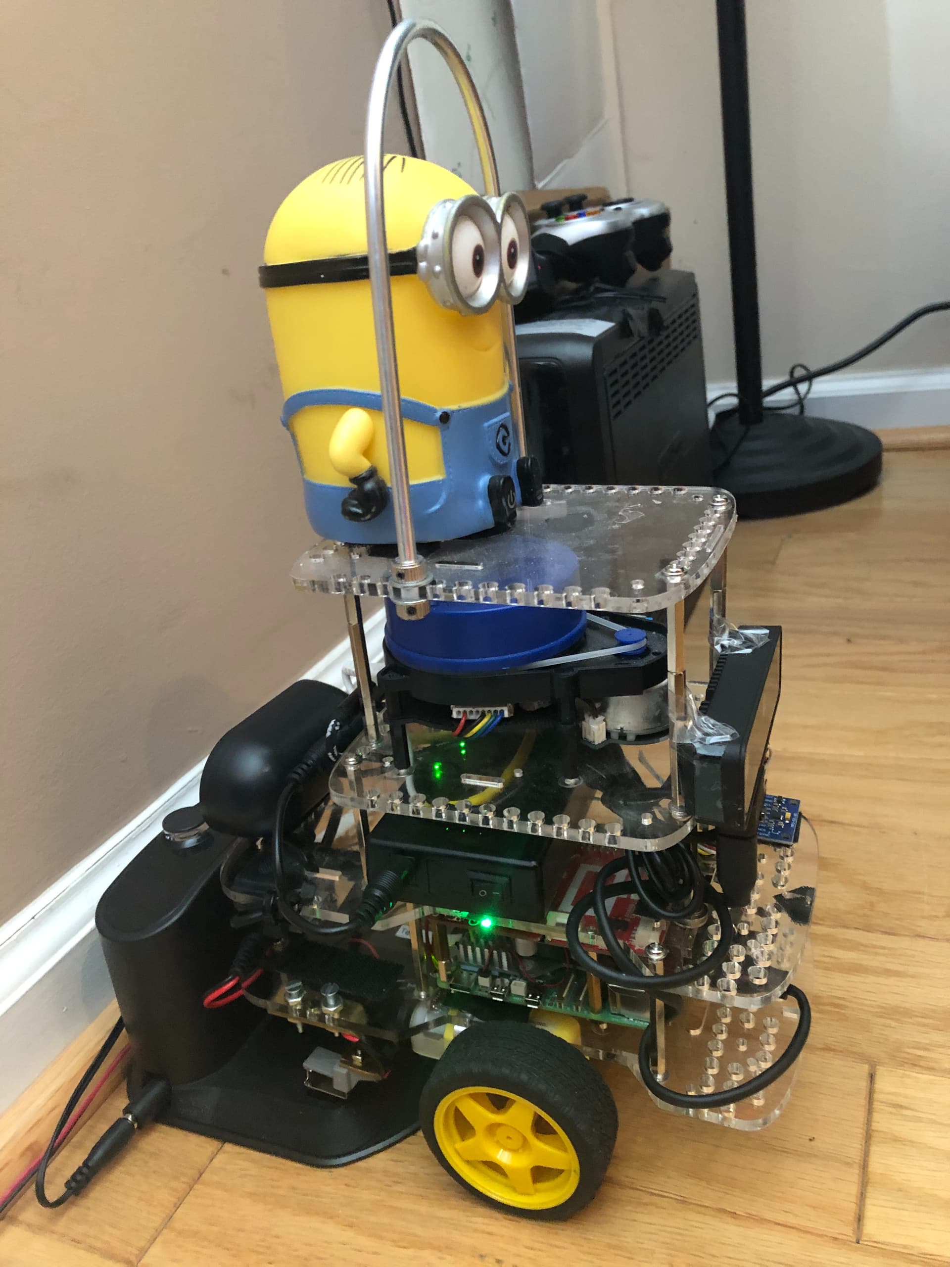
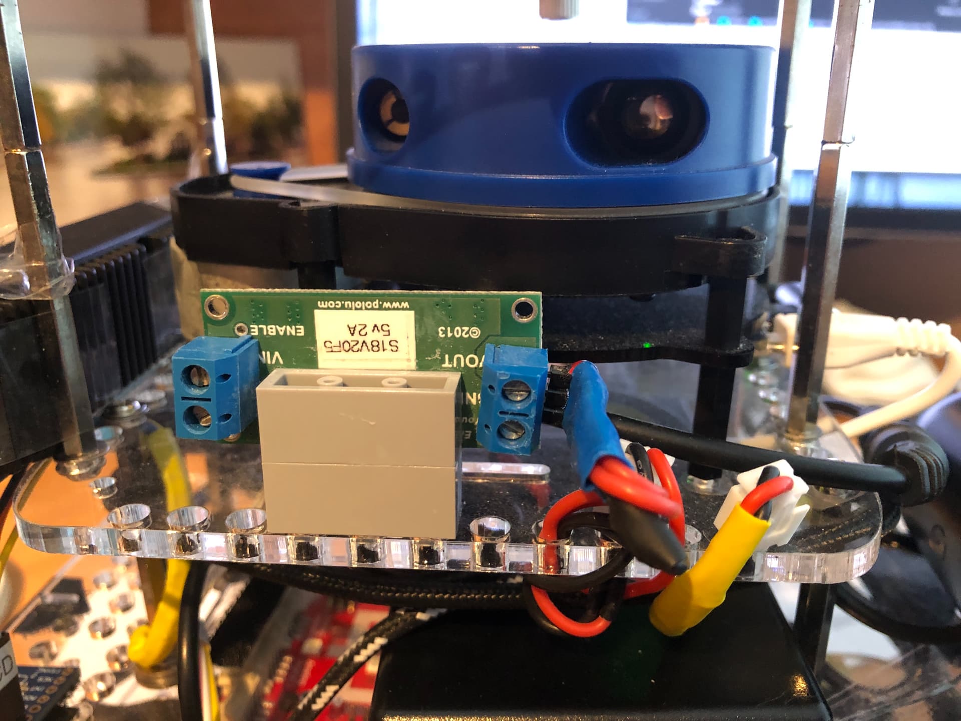
My Raspberry Pi 5 robot has an S18V20F5 Pololu supply driving the LIDAR and Oak-D-Lite stereo depth camera.
I need to be able to disable the supply when the Raspberry Pi 5 is napping (usually on its dock), or when the Pi5 decides the camera and LIDAR are not needed to extend the “playtime”.
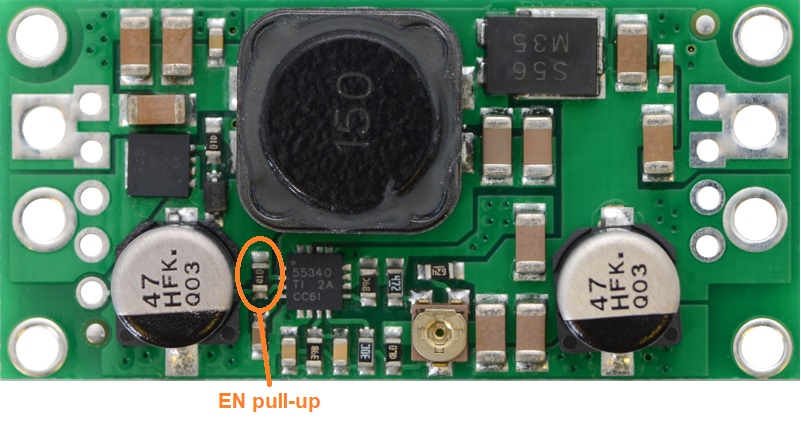
For Raspberry Pi GPIO (3.3v) to enable S18V20F5:
Disable when RPi is off, enable with GPIO pin high 3.3volts.
The spec says the S18V20F5 has a 100k ohm to VIN which in my case is 9.6-12.6v.
Why does my VOM measure 33k ohm when I measure from VIN+ terminal to Enable through-hole?
Doesn’t the “open input” voltage divider have to get the Enable below 0.7v (reliably)?
So GPIO pin to the Enable line, with 2-4k pull-down (to gnd) for 100k ohm pull-up?
If the pull-up is indeed 33k ohm, I need a 1k pull-down to gnd to get .0.35v to the enable when the RPi is “off”?
Does the GPIO pin need reverse polarity protection?
*** GoPi5Go Dave TOTAL LIFE STATISTICS ***
Total Awake:   280.85  hrs
Total Naps:     56.05  hrs
Total Life:    336.90  hrs (since Mar 17, 2024)
Sessions (boot):  45
Average Session:  6.2 hrs
Safety Shutdowns:  3