I am trying to connect one tic with my raspberry Pi with I2C and follow the guidelines according to the manual. I added the dtoverlay=i2c-gpio line to the config.txt file and also connected the tic with SCL to GPIO24 and SDA to GPIO 23.
When I try to run the example code for python on the raspberry pi I get the following error
FileNotFoundError: [Errno 2] No such file or directory: ‘/dev/i2c-3’
It seems like the tic was not detected by the pi. If I run i2cdetect -y 1 I also do not see any device in the list.
pi@raspberrypi:~ $ cat /boot/config.txt
# For more options and information see
# http://rpf.io/configtxt
# Some settings may impact device functionality. See link above for details

# uncomment if you get no picture on HDMI for a default "safe" mode
#hdmi_safe=1

# uncomment this if your display has a black border of unused pixels visible
# and your display can output without overscan
disable_overscan=1

# uncomment the following to adjust overscan. Use positive numbers if console
# goes off screen, and negative if there is too much border
#overscan_left=16
#overscan_right=16
#overscan_top=16
#overscan_bottom=16

# uncomment to force a console size. By default it will be display's size minus
# overscan.
#framebuffer_width=1280
#framebuffer_height=720

# uncomment if hdmi display is not detected and composite is being output
#hdmi_force_hotplug=1

# uncomment to force a specific HDMI mode (this will force VGA)
#hdmi_group=1
#hdmi_mode=1

# uncomment to force a HDMI mode rather than DVI. This can make audio work in
# DMT (computer monitor) modes
#hdmi_drive=2

# uncomment to increase signal to HDMI, if you have interference, blanking, or
# no display
#config_hdmi_boost=4

# uncomment for composite PAL
#sdtv_mode=2

#uncomment to overclock the arm. 700 MHz is the default.
#arm_freq=800

# Uncomment some or all of these to enable the optional hardware interfaces
dtparam=i2c_arm=on
#dtparam=i2s=on
dtparam=spi=on

# Uncomment this to enable infrared communication.
#dtoverlay=gpio-ir,gpio_pin=17
#dtoverlay=gpio-ir-tx,gpio_pin=18

# Additional overlays and parameters are documented /boot/overlays/README

# Enable audio (loads snd_bcm2835)
dtparam=audio=on

[pi4]
# Enable DRM VC4 V3D driver on top of the dispmanx display stack
dtoverlay=vc4-fkms-v3d
max_framebuffers=2

[all]
#dtoverlay=vc4-fkms-v3d

# NOOBS Auto-generated Settings:
dtoverlay=spi1-3c

# Addition for Pololu motor controller I2C
dtoverlay=i2c/gpio


pi@raspberrypi:~ $ ls /dev/i2c*
/dev/i2c-1
It looks like you mistyped; you have dtoverlay=i2c/gpio instead of dtoverlay=i2c-gpio in your /boot/config.txt file. Can you change the forward slash (/) to a hyphen (-), save and restart the Raspberry Pi, run the ls /dev/i2c* command again and post the result here?
Now I get the desired /dev/i2c-1 /dev/i2c-3. However, the example code still does not work and if I run i2cdetect -y 1 I do not get any device there. If I connect the pins with GPIO 2 and 3 instead, I get a device with the address 0e. How would I need to convert it so I can write it into the example code?
Just to clarify, when you connected the Tic’s SDA and SCL pins to GPIO23 and GPIO24 on the Raspberry Pi, respectively, the Python example did not work and running i2cdetect -y 1 did not return anything for you, is that correct?
The i2cdetect command you used is incorrect. When the Tic is connected to GPIO23 and GPIO24, you should be using the command i2cdetect -y 3 in order to scan /dev/i2c-3. See the the man page for i2cdetect for more information on the command and its options, and the overlay documentation for i2c-gpio.
Can you connect the Tic’s SDA and SCL pins to GPIO23 and GPIO24, run i2cdetect -y 3, and post the results here?
The Tic’s I2C address, 0x0E, is 14 in decimal and is the default address value used in the code, so that looks fine and you wouldn’t need to make any changes to the code.
Thanks for your help! Now it works, I am able to actuate the stepper motors. I was able to detect them with i2cdetect -y 3, the tic was on channel 14 as you said.
Hi Amanda, I’m having a similar problem and wonder if you would help me. I get a problem similar to Tobia when I run the Pololu - 12.9. Example I²C code for Linux in Python example in the users guide. I get the error :Traceback (most recent call last):
File “/home/pi/Sketchbook/Pololu_Tic_example.py”, line 55, in
bus = SMBus(3)
File “/home/pi/Sketchbook/smbus2/smbus2.py”, line 280, in init
self.open(bus)
File “/home/pi/Sketchbook/smbus2/smbus2.py”, line 310, in open
self.fd = os.open(filepath, os.O_RDWR)
FileNotFoundError: [Errno 2] No such file or directory: ‘/dev/i2c-3’
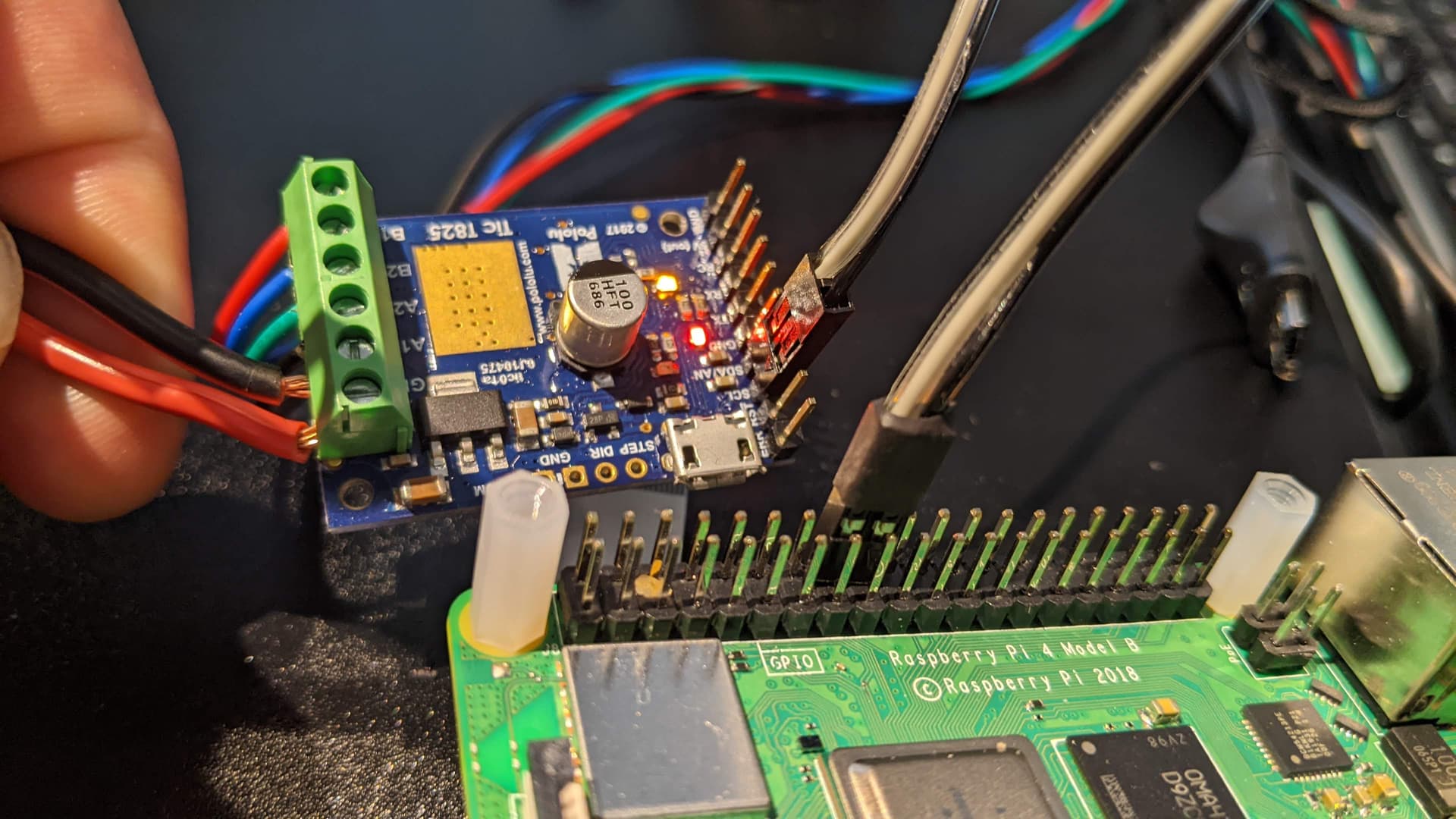
Which version of the Raspberry Pi are you using? Can you post pictures showing the connections between the Tic and Raspberry Pi? Also, can you post the full command you use for the I2C scan?
Can you run cat /boot/config.txt and post the results here?
In your picture, I noticed there is no common ground shared between your Tic and Raspberry Pi devices; you should connect the Raspberry Pi’s GND pin to the Tic’s GND pin. The rest of your connections look fine.
Thanks, Amanda. I am just getting on my feet with RPi, so thanks for your patience with the basic question. I added a ground, and restarted. Still no luck.
This is what config.txt contains:
> lsmith@raspberrypi:~ $ cat /boot/config.txt
> # For more options and information see
> # http://rpf.io/configtxt
> # Some settings may impact device functionality. See link above for details
>
> # uncomment if you get no picture on HDMI for a default "safe" mode
> #hdmi_safe=1
>
> # uncomment the following to adjust overscan. Use positive numbers if console
> # goes off screen, and negative if there is too much border
> #overscan_left=16
> #overscan_right=16
> #overscan_top=16
> #overscan_bottom=16
>
> # uncomment to force a console size. By default it will be display's size minus
> # overscan.
> #framebuffer_width=1280
> #framebuffer_height=720
>
> # uncomment if hdmi display is not detected and composite is being output
> #hdmi_force_hotplug=1
>
> # uncomment to force a specific HDMI mode (this will force VGA)
> #hdmi_group=1
> #hdmi_mode=1
>
> # uncomment to force a HDMI mode rather than DVI. This can make audio work in
> # DMT (computer monitor) modes
> #hdmi_drive=2
>
> # uncomment to increase signal to HDMI, if you have interference, blanking, or
> # no display
> #config_hdmi_boost=4
>
> # uncomment for composite PAL
> #sdtv_mode=2
>
> #uncomment to overclock the arm. 700 MHz is the default.
> #arm_freq=800
>
> # Uncomment some or all of these to enable the optional hardware interfaces
> dtparam=i2c_arm=on
> #dtparam=i2s=on
> #dtparam=spi=on
>
> #added for use with Tic T825 ref https://www.pololu.com/docs/0J71/all#3.2 see 'If you are using a Raspberry Pi'
> dtoverlay=i2c-gpio
>
> # Uncomment this to enable infrared communication.
> #dtoverlay=gpio-ir,gpio_pin=17
> #dtoverlay=gpio-ir-tx,gpio_pin=18
>
> # Additional overlays and parameters are documented /boot/overlays/README
>
> # Enable audio (loads snd_bcm2835)
> dtparam=audio=on
>
> # Automatically load overlays for detected cameras
> camera_auto_detect=1
> #dtoverlay=imx477
>
> # Automatically load overlays for detected DSI displays
> display_auto_detect=1
>
> # Enable DRM VC4 V3D driver
> dtoverlay=vc4-kms-v3d
> max_framebuffers=2
>
> # Run in 64-bit mode
> arm_64bit=1
>
> # Disable compensation for displays with overscan
> disable_overscan=1
>
> [cm4]
> # Enable host mode on the 2711 built-in XHCI USB controller.
> # This line should be removed if the legacy DWC2 controller is required
> # (e.g. for USB device mode) or if USB support is not required.
> otg_mode=1
>
> [all]
>
> [pi4]
> # Run as fast as firmware / board allows
> arm_boost=1
>
> [all]
> gpu_mem=128
And…
lsmith@raspberrypi:~ $ ls /dev/i2c*
/dev/i2c-1 /dev/i2c-20 /dev/i2c-21 /dev/i2c-22
lsmith@raspberrypi:~ $ i2cdetect -y 3
Error: Could not open file /dev/i2c-3' or /dev/i2c/3’: No such file or directory
Can you specify the bus parameter for dtoverlay=i2c-gpio in /boot/config.txt then restart to see if that fixes the issue? The whole line should be dtoverlay=i2c-gpio,bus=3. For some reason your Raspberry Pi is using i2c-22 instead of i2c-3, which is usually the default bus number that’s dynamically assigned. (You can find more details looking at the “i2c-gpio” section in the README for Device Tree overlays for the Raspberry Pi if you’re interested.)
Hi, Amanda. I had to step away from this project a few months ago, but I am back at it. I have now added the line dtoverlay=i2c-gpio,bus=3 to the config.txt. When I run ls /dev/i2c* I see:
When I run the Python code example provided in section 12.9, I get the following result:
>>> %Run -c $EDITOR_CONTENT
Traceback (most recent call last):
  File "<string>", line 53, in <module>
  File "<string>", line 43, in get_current_position
  File "<string>", line 39, in get_variables
  File "/home/lsmith/.local/lib/python3.9/site-packages/smbus2/smbus2.py", line 658, in i2c_rdwr
    ioctl(self.fd, I2C_RDWR, ioctl_data)
OSError: [Errno 6] No such device or address
This gives me the impression that the i2c device is not detected. I have ground connected between the Tic and the RP1 4B, and I have SDA on the Tic connected to GPIO23, and SCL connected to GPIO24.
I should add that the motor works when I use the tic software over USB. I have tried connecting to the Tic at bus 22, since you suggested that is where it may be, but no luck. I can try other GPIO pins if that is an option, but I understood that GPIOs 23 and 24 were the preferred pins.
I will be away until Friday, so if you provide suggestions, I won’t be able to implement those until that time.