Raspberry Pi 3 Under-voltage event at startup

I absolutely love the small size of the Pololu S18V20F5 switching supply which I installed on my personal robot, but I have a concern about the supply at startup.

My circuit consists of 6 NiMH 5000mA 1.2v C-cells passing through the Pololu “Standard” Power Switch (SV item 750) to the S18V20F5 5v supply which powers a Raspberry Pi Model 3B.

At idle the Raspberry Pi is drawing 280mA and the supply shows 5.01v. When supplying about 1A the supply voltage drops to 4.88v which is still within the operating limits of the Raspberry Pi.

(The Raspberry Pi requires 5v +/- 5%, and will report an under-voltage event at 4.75v)

When I boot the Raspberry Pi the processor reports that an under-voltage event occurred during startup.

BTW, The unregulated voltage from the batteries at startup ranges from 8.5v to 7.5v

When I boot the Raspberry Pi from a 5v 2A “wall wart” the processor reports a clean startup with no under-voltage events.

To see the status: vcgencmd get_throttled

throttled=0x50000 means throttling event occurred and under-voltage event occurred
throttled=0x00000 means no under-voltage events were seen

(Note: - I think the get_throttled status is only available on the Pi 3)

Anyone else seeing an under-voltage event at boot?

1 Like

Can you post some pictures of your setup that show all of your connections (a wiring diagram might be helpful as well)? Does the under-voltage event occur every time the Raspberry Pi is booted, and is that the only time it occurs? How are you measuring the current draw? The boot process might be drawing a larger spike in current that is causing the under-voltage error. If that’s the case, you might try adding some large capacitors to the output of the regulator.

Also, could you try powering your Raspberry Pi from the wall power adapter through the regulator (e.g. connecting the wall adapter to the input of the regulator and the Raspberry Pi to the output of the regulator)?

Here is the circuit diagram on Flickr: 7.2v → Pololu SV switch → ACS712 Current Sensor → Pololu S18V20F5 5v 2A switching supply → Raspberry Pi 3
PogoPower

Here is a photo showing Pololu 5v 2A switching supply and USB socket

Here is a photo showing the Pololu SV push button switch and the ACS712 Current Sensor Pigo top view - (Rug Warrior Pi Robot)

This photo from the rear of the bot shows four of the batteries, the Pololu SV switch (upper right), and the ferrite core right next to the connection to the Raspberry Pi (black cyl. around the green wire)

I tried a 10v 1000uF at the 5v output of the S18V20F5 - no cigars.
I tried the 10v 1000uF across the unreg 8.2v (steady state) input to the S18V20F5 - still no cigars.

I’ll try the 5v 2A wall wart input to the S18V20F5 test tomorrow, but that is perhaps not a totally valid test as the regulator might be in a slight step up mode, no? Anyway - I’ll give it a try tomorrow and see what happens.

The Issue:

  • Powering with a Gizmo Junkies MX12L2-0502000WW:
    ** boots and runs fibanacci.py on one core with no under-voltage, no throttling - NEVER.

  • Powering with a Pololu S18V20F5 5v 2A switching supply:
    ** shows under-voltage during boot, ALWAYS
    ** under-voltage running fibanacci.py on one core, ALWAYS, CONSTANT (or FREQUENT)
    ** under-voltage events even at idle, SOME

  • there is a 0.25 v drop in the 8" USB cable from the pololu to the Pi that is causing under-voltage when the Pololu supplies 5v.

The specs:

  • The wall wart states it supplies 5.3v at 2.0 Amps
  • The Pololu supply spec is 5.0v +/- 4% (4.8v - 5.2v)
  • The Pi3 supply spec is 5.0v +/- 5% (4.75v - 5.25v)
  • Drok OLED Digital USB Multimeter
    ** Voltage : DC 3.50-9.99V; accuracy: ±(0.3% + 1words)
    ** Current : DC 0.00-3.00A; accuracy: ±(0.5% + 2words)
  • Digital Multimeter DT830B (all-sun) accuracy: ±(0.5%)

Running Pi3 on the wall-wart - no under-voltage, BUT!:

  • The wall wart supplies a quite constant 5.44v at the wall wart
  • Voltage measures 5.27 at the Pi3 40 pin connector at idle
  • Voltage measures 5.22 at the Pi3 40 pin connector running fib.py
  • Pi3 draws 0.31A at idle,
  • Pi3 draws 0.47 Amps running fib.py on one core at 100%

Running Pi3 on Unregulated (8.5 - 7.5v) Battery ->Pololu supply:

  • Voltage at Pololu out shows 5.01v at 0.28 A with Pi3 at idle
  • Voltage at Pi3 40pin connector reads 4.88v with Pi3 at idle
  • boot shows under-voltage occurred
  • Voltage at Pololu output shows 4.98v at 0.45A running fib.py
  • Voltage at Pi3 40pin connector varies from 4.60-4.86 running fib.py
  • Pi3 draws 0.45A running fib.py throttled to 600MHz, CONSTANT UNDER-VOLTAGE

Wall-Wart ->Pololu supply data:

  • The Pololu supply draws 0.34A at 5.44v from the wall-wart (Pi3 idle/boot)
  • The Pololu supply draws 0.45A-0.52A at 5.44v (Pi3 running 1 core 100% fib.py)
  • The Pi3 shows under-voltage events when powered from the wall-wart powered Pololu supply
  • (frequently at idle, and constantly running fib.py)
  • Pololu is supplying 4.97v at 0.32A at idle
  • Pi3 40 pin connector shows 4.82 at idle
  • Pololu is supplying 4.97v at 0.37A-0.46A running fib.py
  • Pi3 40 pin connector shows 4.77-4.80v running fib.py
2 Likes

So here is the scoop - and what an “educational experience” this robot has become.

Who knew that 6 inches of cable could drop 0.2 - 0.3 volts. I didn’t know that I needed to spec a variable voltage regulator to allow for the voltage drop in a 6 inch cable.

The Gizmo Junkies wall wart is “spec’d” at 5.3v 2A and puts out 5.44v at the wall wart. By the time the juice gets to the Pi down the cable Gizmo Junkies provided with the wall wart, the voltage is at … wait for it … can we guess? exactly 5.25 volts - the upper limit of the Raspberry Pi power requirement specification. Talk about a thorough design - I am impressed.

The Raspberry Pi power requirement spec is 5v +/- 5% which gives a seemingly wide range from 4.75v to 5.25v.

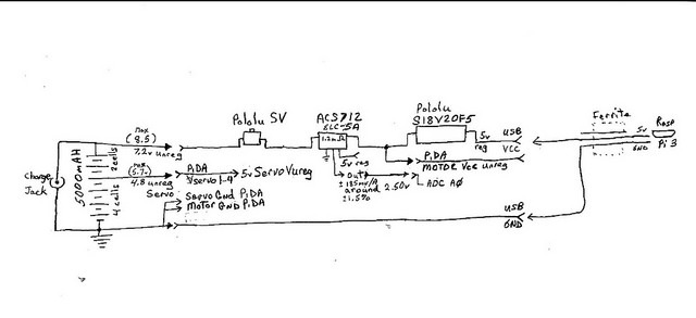
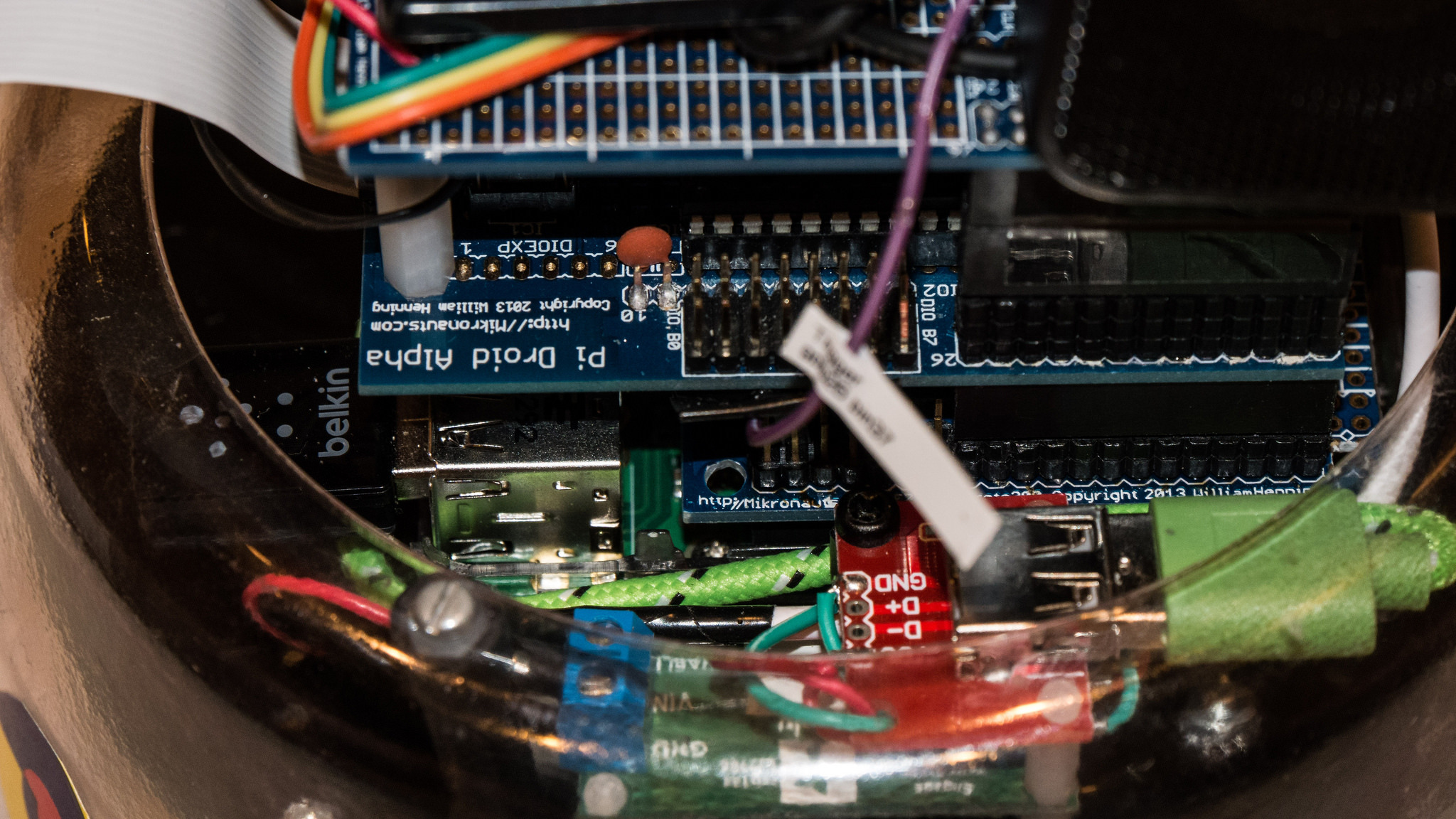
I was very happy with my Pololu S18V20F5 5v 2A step-up / step-down switching supply when I saw 4.97 to 4.99 volts coming out. I never thought to measure what the voltage is at the Pi six inches away. I bought one of the shortest USB to mini-USB cables I could find on Amazon. Pretty ones too! Turns out at idle the voltage reading at the 40 pin connector is 4.82 - 4.86v with that 6" cable. When I cranked up fibonacci.py at 100% of one core and pulled 500mA of that 4.97 to 4.99v through the cable, the voltage varied from 4.67 to 4.77v at the 40 pin connector.

The Raspberry Pi says “wait just a minute there cowboy” at exactly 4.75v declaring an under-voltage event and throttling the processor back from 1.2GHz to 600MHz, which draws a little less current, which means slightly less voltage drop in that 6 inches of two tiny wires. The Pi3 sees the voltage go up and eventually runs the clock back to 1.2GHz and the trouble comes right back.

I grabbed my thirty year old rolls of “hookup wire” and built me a 6 inch twisted pair cable and soldered the hair thick conductors of the mini-USB connector at the end. Now my Pi 3 is drinking a solid 4.93v at idle and 4.90 at 500mA running that fib sequence on one core. The proc says it is starting to sweat (65.5 degC) but did not register an under-voltage at boot or under this load.

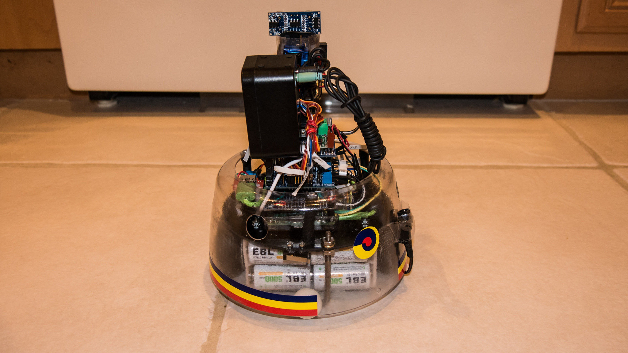
In fact - I just ran four remote WiFi ssh shells, two running fib.py, one looping a status which reads the HC-SR04 ultrasonic sensor, checks the ADC readings of the IR sensor distance sensor, the main battery voltage, and total current draw (635ma at 7.4v), and the last shell looping checking the vcgencmd to get proc temperature (I stopped everything at 80.1 degC), proc frequency (1.2GHz) and the throttled flags (all 0x00000 - no under-voltage, no throttling!).

The board above the Pi 3 got pretty warm, and the 40pin connector “5v0” went down to 4.88v, but the bot survived the load with no “events”.

I’m going to buy the S18V20ALV variable output supply so that I can have more safety factor, and use the “pretty” cable I started this journey with.

Just a note for anyone reading - Brandon in support responded quickly and showed great interest. A big thank you to him.

1 Like

Hello.

Thank you for documenting the testing you did so well and for the kind words. I am glad you were able to track down the problem and find a possible solution. I would be interested in hearing how your testing goes with the S18V20ALV adjustable regulator as well.

Brandon