I noticed that the Zumo 2040 battery measurement code returns a value much higher than the actual voltage I measure with a multimeter. I measure 5.2V with my multimeter but 5.9V shows up at the top of the default µPython splash loader that runs on device startup. Has anyone else noticed this?
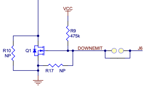
When investigating this issue, I noticed that the Zumo 2040 schematic shows a 475k resistor (R9) between DOWNEMIT and VCC.
I can see why you might want to have a pull-down on DOWNEMIT (like on the 3π+ 2040) to make sure that that MOSFET driving the LED emitter for the line sensor would default to off when DOWNEMIT isn’t being driven by the RP2040 but I can’t see why you would want a pull-up on it (like on the Zumo 2040). Actually on both bots, I would have thought that the 10k resistor at the bottom of the battery level voltage divider connected to the same pin would have been enough anyway. Maybe having the extra pull-down on DOWNEMIT was done so that the user can cut the link connecting it to BATLEV which would then leave the MOSFET floating when not being actively driven by the RP2040 unless the extra pull-down resistor was in the circuit.
As I was porting the Zumo 32U4 Arduino Library to the Zumo 2040, I ended up writing the following code in an attempt to compensate for the impact of R9 on the battery level measurement. I did end up using floating point for now since it makes things much easier and the routine isn’t super fast anyway since it needs to take 10 ADC measurements:
    // Calculate the voltage at Pin 26.
    float voltP26 = (3.3f * (float)sum) / ((float)sampleCount * 1023.0f);
    // The current through the 10k resistor (R29) connecting p26 to ground [Ohm's Law].
    float curr10k = voltP26 / 10000.0f;
    // The current through the 475k resistor (R9) connecting p26 to 3.3V [Ohm's Law].
    float curr475k = (3.3f - voltP26) / 475000.0f;
    // The current flowing through the 10k resistor (R29) is the sum of the currents through the 100k resistor (R28)
    // and the 475k resistor (R9) [Kirchhoff's Current Law].
    float curr100k = curr10k - curr475k;
    // The voltage of the battery is equal to the voltage at Pin 26 + the voltage across the 100k resistor (R28).
    // [Kirchhoff's Voltage Law and Ohm's Law].
    float voltBattery = voltP26 + curr100k * 100000.0f;

    // Return the battery voltage to the closest mV.
    return (uint16_t)(voltBattery*1000.0f + 0.5);
This gave a measurement much closer to what the multimeter measured:
Multimeter: 5.1V
Zumo Code Above: 5.3V
Error: +4% (probably within error tolerance of resistors used)
Am I root causing this issue correctly and is my math to workaround it correct?
Edit: I realized that I should have added snippets of the related schematics so I went back in and did this.
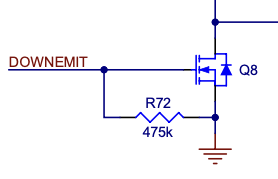
As you probably guessed, the reason for the 475k resistor on DOWNEMIT on both the 3pi+ 2040 and Zumo 2040 Front Sensor Array is to ensure the MOSFET gate doesn’t float in case it’s disconnected from an I/O. On the 3pi+, that can happen if you cut the trace under the front expansion header to disconnect DOWNEMIT (DNE) from GP26. For the Zumo front sensor array, that might happen if you choose to use it in a custom application (something other than a Zumo 2040) that doesn’t connect to that pin.
I’m not exactly sure about the reason we pulled it in opposite directions on the two robots, but I think the idea was to make the emitters turn on by default (making the emitter control pin largely optional) when using the Zumo front sensor array in a custom application. Meanwhile, the 3pi+ reflectance sensors are built into the main board, so we wanted those to be off by default if disconnected to avoid wasting power. On both robots, DOWNEMIT is normally connected to GP26 along with the battery level divider, so the down emitters are off by default on a stock Zumo 2040 (since the divider pulls down more strongly than the 475k pulls up).
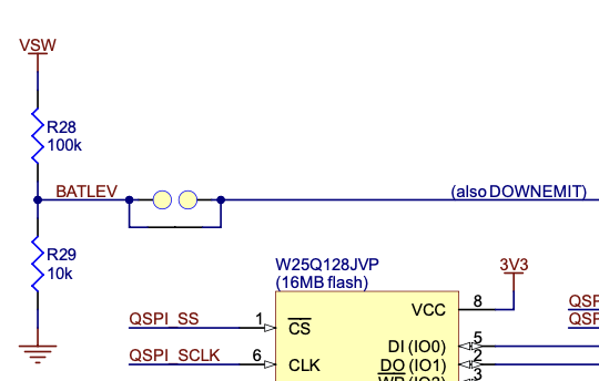
It looks like our library code for both robots simply multiplies the analog reading from GP26 by 11 to calculate the battery voltage, which assumes only the divider is there (100k+10k) and ignores the impact of the DOWNEMIT resistor. This means the calculation will be a little inaccurate in both cases when DOWNEMIT is connected.
On the 3pi+, a 475k pull-down in parallel with the 10k makes it effectively a 9.79k bottom resistor, so the conversion factor should actually be about 11.2 and the calculated value is about 2% low. That shouldn’t be a big deal.
On the Zumo, the 475k pull-up isn’t in parallel with the 100k (they go to different voltages), but I guess it does have a bigger effect on the GP26 measurement since the top resistor has a higher resistance. It looks like the calculated value can be up to 15% high when the battery voltage is 4V, dropping to under 10% high at 6V. It’s possible we overlooked that when deciding to make it a pull-up!
With that in mind, your math and code look correct to me. Of course, fixing the calculation to account for R9 means it will be inaccurate if the front sensor array is removed. (Maybe there should be a parameter to indicate whether the sensor array is installed and adjust the calculation accordingly, or just two separate versions of the function?)
Thanks for the quick response. It clarifies what I have been seeing and gives me some background on why things were done the way they were.
Good point! I will look into that for my port. I just built up a Zumo last night which hasn’t had the front sensor array attached since I am using it to test my port of Pololu’s Balancing sketch. I hadn’t even tried running my battery calculation on that bot yet