Is there anything specific about the motor driver and power distribution board #3543 for the Romi chassis that makes it most suitable for the Romi?
I have a mega2560 that I’d like to use with the chassis and it has its own motor drive expansion board. I’m not trying to “cheat” pololu here. It would just seem to be easier for me to have a motor controller match my board rather than find a motor controller that matches the chassis.
Also, when considering a 3pi vs the romi, it seems like I’m missing out on a lot of the built-ins (sensors, led’s, power switches, lcd screen). But if I’m interested in really building my own thing and not just line following and object avoidance, I think I’m better off with the less expensive option.
The #3543Motor Driver and Power Distribution Board for the Romi Chassis is intended to make it easy to get your robot up and running quickly. Along with a power switch and built-in motor driver, the board has a powerful switching step-down regulator that can supply 2.5A continuously at 5V or 3.3V, and makes it convenient to connect to the battery terminals. With all of the features built into the board, you essentially just need a microcontroller and any additional sensors you want.
However, the Romi chassis is intended to be a general purpose robot, and you could certainly use the chassis with your own electronics. If you want to use your own motor driver, I would recommend considering the #3541Power Distribution Board for the Romi Chassis, which is less expensive than the #3543 board, but still offers a convenient way to connect to the battery terminals, a power button/switch, and easy access to various power busses.
By the way, when choosing your motor driver/controller, be sure to choose one that is appropriate for the motors. We generally recommend choosing a motor driver that has a continuous current rating equal to or greater than the stall current of your motors. The #3543 Motor Driver and Power Distribution Board uses two DRV8838 motor driver carriers, but if you are looking for a driver with an Arduino shield form factor, you might consider the DRV8835 Dual Motor Driver Shield for Arduino, which is rated for slightly less than the stall current of the 120:1 HP Mini Plastic Gearmotors that come with the Romi Chassis, but should be fine if you avoid stall conditions.
What frequency do you recommend for PWM to drive the Romi motors? I’m using 10KHz, but the speeds as measured by the shaft encoders seem to vary a lot.
We typically use 20 kHz PWM frequencies because it is above the threshold for human hearing. What kind of variation are you seeing? Could you post a data set that shows the problem (preferably with no load on the motors)?
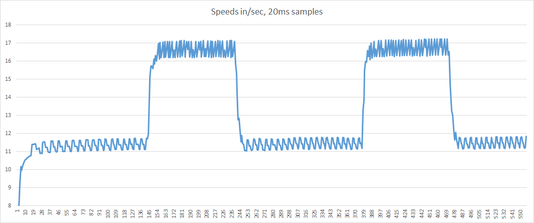
Thanks for your quick reply. I’ve tried 20KHz PWM frequency now and there’s still an oscillation of about 1"/sec (motor tested at two speeds – 11 in/sec and about 16 in/sec – up on blocks, so it’s unloaded except for the wheel). I intend to use these values to calibrate the PWM settings for inches/second speeds, then use PID controls to ensure the two motors run at the same speed.
The oscillation frequency appears to vary with the motor speed, so it might be something like the wheel wobbling (and might disappear when the chassis is running on the floor).
The graph showing this is pasted here. Thanks for any word on this.
Can you tell us more about your system? What are you using to generate control signals and drive the motors? What are you supplying for motor power and what duty cycles did you use for your PWM signals? Additionally, can you generate more data that shows the speed of each motor with their wheels removed?
By the way, in case you were not already aware: the speeds of brushed DC motors like the ones used in the Romi can vary by as much as ±10% from unit to unit.
Thanks for your interest in this. I’m using a Romi chassis with the Romi motor controller and power management board and the Pololu shaft encoders. I’m driving it with a custom processor board based on a PIC32MX part. At the slower speeds, the PWM duty cycles are about 10% to 20%. I’ve generally been careful to use fully-charged AA batteries through the testing, so as not to get bit by a bad result based on low power.
I have seen that variance between motors – I calibrate each motor separately and use parameters for generating the PWM duty cycles that are specific to each motor.
I’m wondering now whether a slower PWM frequency and longer duty cycles might not work better at the low speeds I’m trying to run.
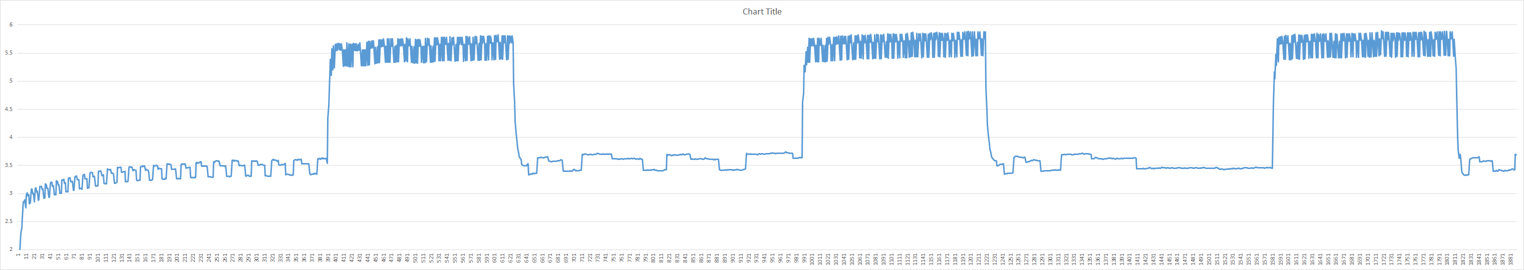
It will be hard to remove the wheels, but it does make sense to try that. I have more data for different speeds, however, that can show a faster oscillation at slower speeds, so wheel wobble might not be an issue (unless it’s some resonance that gets hit at particular speeds).
I’ve attached another graph that shows worse behavior at slower speeds (where I want to operate it) – especially around 4"/sec (about 1/2 rev/sec). I’ve checked to see if the wheels are hitting something, but they are completely free to move.
It would still be good to see some data without the wheels on the motors, and it might also be useful to see how the speed varies when the motors are run at 100% duty cycle.
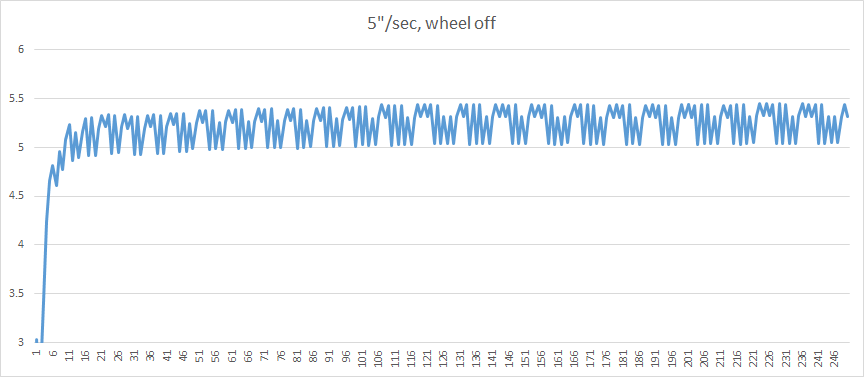
I took one of the wheels off and ran it at low speed and at the fastest it’s able to go (don’t know the duty cycle, but it should be close to 100%).
Results in the attached graphs – at slow speeds the speed is still ragged and variable. It’s much worse at the higher speeds.
I’m wondering if this isn’t something in the motors’ gears or bearings. In one of the earlier graphs there’s a repeating pattern at low speed that looks like stick/slip that might be a gearing issue.
In any case, I’ve found that I can run the chassis on the floor at slow speeds with control parameters that make it run alright – it wiggles a bit and won’t quite move in a straight line, but it is alright for what I need now.
The data you are showing does not sound obviously bad to me, but I also want to learn more about your system. Can you describe how you are reading the Romi encoders? If the part of your code that reads the encoders and interprets the counts is not too messy, could you post it here?
I use PIC32 input capture hardware driven by one of the encoder signals – the other signal is used to tell what direction the motor is going. That gives me 360 interrupts per revolution. The capture hardware captures a timer that gives me the time between interrupts, which gives me the speed. Pretty straightforward. The program main loop counts 5ms ticks to store the speeds in an array every 20ms or more. I read the array out with the Microchip debugger and generate the graph in Excel.
Here’s the capture interrupt handler; it’s not too ugly to share. Thanks for the review.
// IC1 corresponds to DRV_IC_0, RIGHT motor
void __ISR(_INPUT_CAPTURE_1_VECTOR, ipl3AUTO) _IntHandlerDrvICInstance0(void)
{
    int8_t tmp;
    uint16_t capturedValue;
    double dduration;
    double delta;
    double omega;

    capturedValue = DRV_IC0_Capture16BitDataRead();     // get timer value upon capture
    cpr_count++;

    // use previous captured timer to handle timer overrun
    if (capturedValue <= captured_valuer) {             // check for timer rollover (just one rollover, note)
        dduration = 48000 - captured_valuer + capturedValue; // max count is 48000 -- use that when timer rolls over
    } else {
        dduration = capturedValue - captured_valuer;
    }
    captured_valuer = capturedValue;                    // save current captured value for use in next interval
    total_timer = dduration * 0.00000066667;            // (this was -> tmr1 is 65536 counts per 10.9ms -> .16632us/tick)
    if (total_timer != 0.0)                             // tmr1 is 48000 counts out of 32ms -> .6667us/tick
        revr = 0.002778 / total_timer;                  // each tick is 1/360rev, this gives rev/sec
    else
        revr = 0.0;
    if (revr > 12.0)
        revr = 0.0;
    speedr = 8.658 * revr;                              // each rev is 8.658in, converts rev/sec to in/sec

    // need flag here to allow main loop to print debug data for speed, time, etc.
    data_availabler = true;

    // construct current right encoder state -- will be either 1 or 3
    tmp = 2;  // <-- IC1 input is upper bit in encoder value
    tmp |= ERBStateGet();
    encoder_stater = tmp;

    // IC1 is always 1 in this interrupt routine
    // ERB is 1 when going forward, 0 when going backward -- use that logic
    if (tmp == 2)
        dirr = -1;
    else
        dirr = 1;
    // now factor direction into rev and speed values
    revr = dirr * revr;
    speedr = dirr * speedr;

    PLIB_INT_SourceFlagClear(INT_ID_0, INT_SOURCE_INPUT_CAPTURE_1);
}
I suspect you might be seeing the variation in the physical dimensions of the encoder poles (e.g. the magnetized “wedges” of the disk that are sensed by the encoder). Some of those wedges could be a little bit bigger than others.
Because of that, it would be better to measure the time elapsed over one entire rotation of the encoder disc, instead of looking at smaller rotations and calculating speed after every interrupt like what your code is doing now.
Thanks, that’s a great idea. That would be 6 counts for one output, is that right? I’d want to do the same thing for updating the position of the chassis, then, too.
Thanks again. I’ll post results when I can get it set up.
Yes, 6 counts per revolution of the motor shaft for a single output channel is correct (this would entail monitoring both the rising and falling edges of the pulses on that output signal).
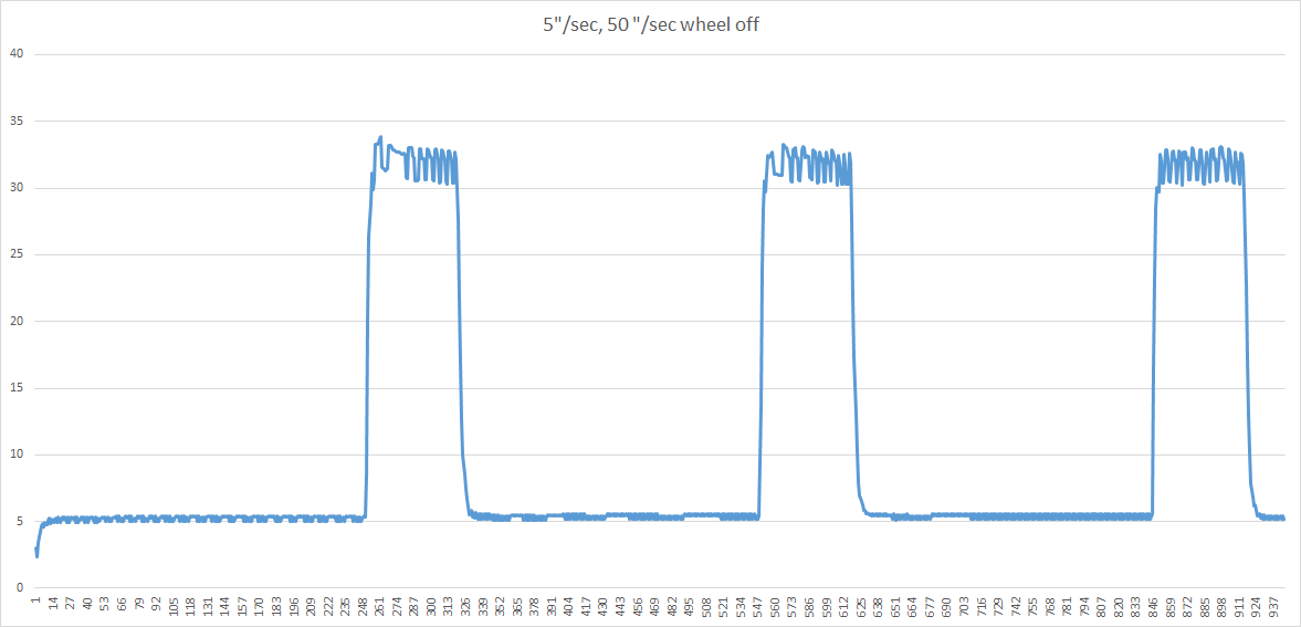
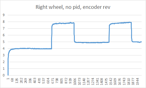
You definitely called it – attached image shows speeds when I use the full rotation of the encoder wheel as the basis for the measurement (I’m still using the rising edge only and counting 3 intervals to determine that a full encoder rotation has occurred; I’ll use that same full rotation as the basis for odometry measurements).
The test run starts at 4"/sec, then goes between 8"/sec and 5"/sec. I haven’t calibrated the speed carefully yet, but it looks like what I’m after.
Thanks for your help with this, and for sticking with this issue.