Hello,
i just have some questions about 3pi robot circuit diagram if it possible …
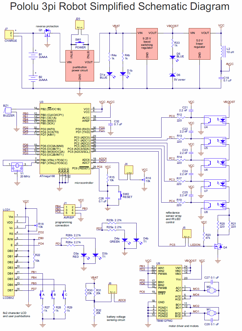
- why you used a coil in the power circuit ??
- what is AVCC and why you didn’t just use VCC ?
- Capacitors C21, C22 , C23 … How you connecting a capacitors to a DC current in series and the current is flowing …!? i think it’s suppose to the capacitors prevent the DC current and allow only AC ??
- why you didn’t connect sensors in parallel ??
- TB6612FNG … you connected both PWMA, PWMB to VCC 5 volts , so how did you control the speed if it’s a constant value ( VCC ) ?? i think it’s supposed to be connected to the PWM PINS in the microcontroller or how it works ??
i’m sorry for my too much questions but i’m interesting on learning how my 3PI Robot works 
cheers.
Hello.
The inductor shown on the schematic is used to stabilize the voltage provided to the AVCC pin on the ATmega328P microcontroller. AVCC is the power supply for the ADC (analog-to-digital converter). This is recommended in Section 24.6.2 and Figure 24-9 in the datasheet for the microcontroller.
The capacitors you mentioned are part of the reflectance sensor circuit. You can read more about how this circuit works in the “Digital inputs and sensors” section of the 3pi User’s Guide, which is linked to on the resources tab of the 3pi’s product page.
The IR emitters on the sensor array are connected in series because VBOOST is higher than the forward voltage drop across the string of emitters and the configuration is more efficient than connecting them in parallel and using a much larger current limiting resistor for each one.
There is a “truth” table for the TB6612FNG on page 4 of its data sheet that shows the configuration of the H-bridge for given input states. If PWM is held high, it is possible to get all 4 output modes (CW, CCW, Short Brake, and Stop) using only the IN1 and IN2 pins, which saves an I/O pin on the microcontroller.
-Nathan
Hi Nathan … thanks for your answer , i understood a bit but there are some questions still not
how in sensors circuit capacitors are connected with power in series and it’s working ?? how the current flowing ??
and the last question please … in the power circuit what’s the use of the zener diode ??
thanks alot
[quote]how in sensors circuit capacitors are connected with power in series and it’s working ??[/quote]That is explained in the links Nathan posted. Study them and you will be a much wiser person!
The 5V zener diode ( D6 ) is used to prevent the blue LED from turning on if the boost regulator is not functioning correctly and the voltage on VBOOST is too low.
-Nathan