Hey!
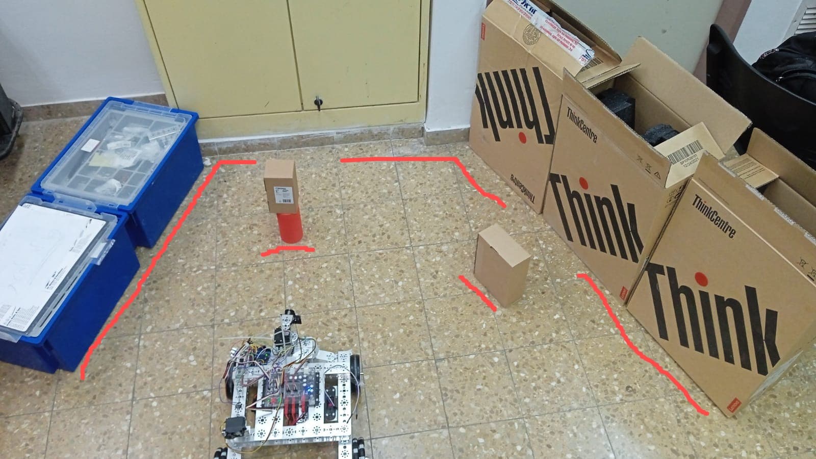
I have a VL53L1X optical sensor for distance detection, I collect its distance readings and try to represent with them some kind of map of the area it sees using Matlab software, I do this by rotating the sensor on a servo motor by 180 degrees, the degrees of the servo together With the reading of the distance I convert to the form of a Cartesian axis system. The problem is that when the sensor detects an object in front of it, it draws its edges and boundaries in a continuous conical shape together with the background behind it and not in separate sections that are more suitable for the background in relation to the object. what could be the problem? It may be related to the viewing angle of the sensor which is too large and needs to be reduced? If so, how do you do it?
I use this module: Pololu - VL53L1X Time-of-Flight Distance Sensor Carrier with Voltage Regulator, 400cm Max
I am attaching a picture to illustrate the matter:
I get the following drawing:

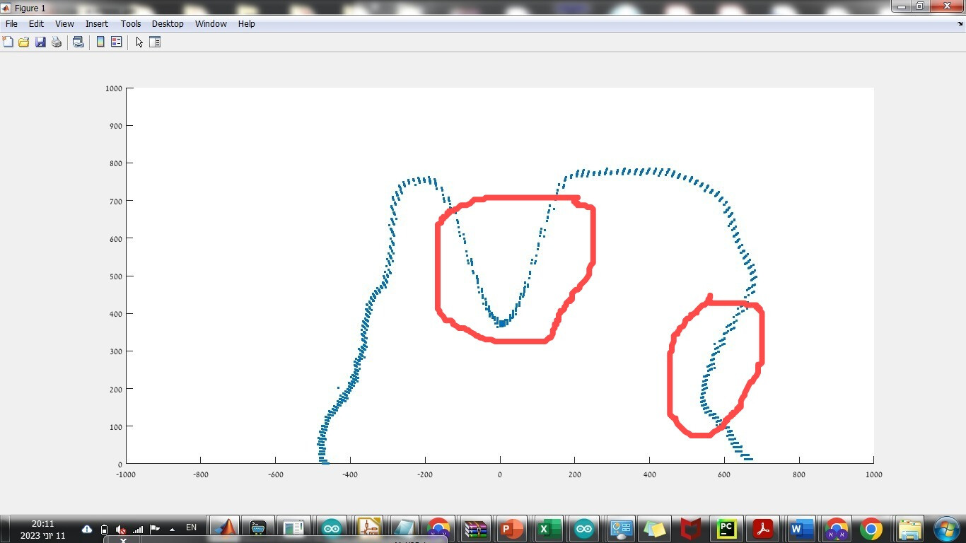
On the other hand, this is what I would like and wish to receive: