I’m wanting to get a reflectance sensor array possibly with 4 sensors. Looking at the above I can’t figure out for the life of me why you have 7 pins plus GND, VCC & CTRL. 4 sensors and 7 pins ? I’ve been staring at the picture for 30 minutes and I’m still clueless.
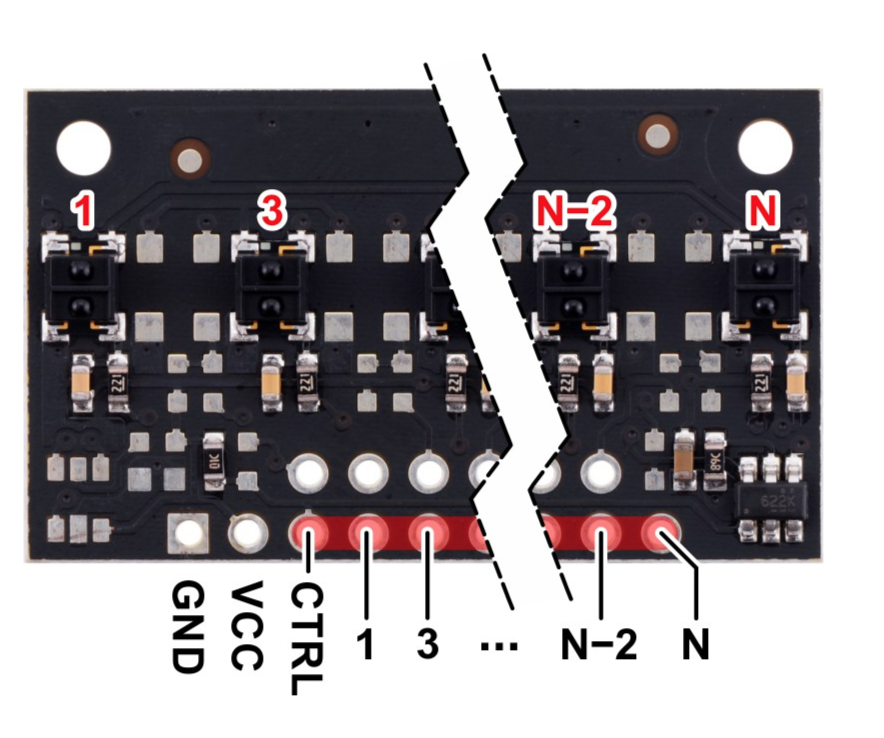
There are unused pins on the medium-density (MD) QTRX-MD-04RC array you have because we use the same PCB for a high-density (HD) QTRX array with seven senors (the QTRX-HD-07RC). That also explains why there are many empty pads from unpopulated components on your board. Which pins are connected to which sensors is indicated by this picture from the QTRX-MD-04RC product page.
I am not sure how or why you would specifically need to connect a 5x2 female header to the QTRX-MD-04RC. Since the board only uses the bottom row of pins, a 1x7 header would probably be ideal. Or you could just solder wires directly to the board and then attach those to whatever header you want.
I suggest reviewing our Arduino QTR sensor library’sREADME.md file as well as the comments in the relevant example programs.
I was thinking that the analog pins 1,2,3,4 are on two rows? However looking at the picture again, it looks like the pin order is: 1, 3, 2, 4 (I just realised N, N-2 means this)