Hi everyone. Im working on line follower robot project.
I dont want prepared code and library I’d like create my own code.
Im using QTR sensor ( 8A and 8RC using one of them it doesent matter )
I want to move the robot according to the values I see.
But i have a few problems.
Problem 1 -)
If i dont send trigger to sensor in the void setup part, I can’t see meaningful values.
The values dont changing on the black line. I did not understand the logic of this work and i wonder about it
Problem 2-)
I created simple code logic.(with if else). My motors are high speed therefore i think robot missed the line.
while wheels in the air code is working but on the floor robot missed the line
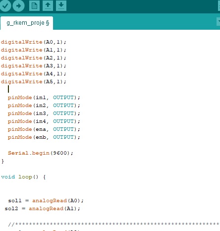
here is my code ; ifelseyapi.ino (3.6 KB)
and im trying different code logic such as read digital values and im using position formula
(0left1+ 1000left2+2000*middle1+3000…/(left1+left2+middle1+…) and im trying to move the robot according to error values but it doesent working.
I think maybe it is related about sensor return duration. How can i fix it ?
The QTR-8A and QTR-8RC are different sensors with different ways to read their outputs. Trying to read the QTR array incorrectly could be the source of the issues you are having. Which QTR sensor are you using?
Dear Jonathan thanks for your attention.
Im using QTR 8A sensor.
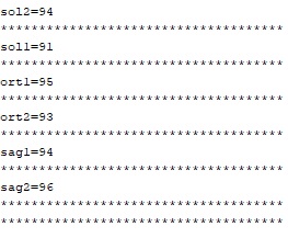
This values all sensors on the white floor
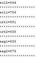
this values all sensors on the black line
is there any problem in here ?
Those values is changing with floor color but i can’t control that according to my desire.
motors do not respond quickly. Maybe the sensor values dont reach instantly.
Those values are about what we expect for sensing a white floor or black line. We generally expect the response time of the QTR-xA arrays to be fast enough for basic line following. You mentioned that you suspect your robot was moving too quickly to notice the line in time before reacting to it, which makes sense since your code seems to work when you hold your robot in the air. In general, a reasonable approach to making a line following robot is to start following lines at a slower speed and get the robot following the line accurately first before gradually increasing the speed (and, if applicable, tuning your PID constants). Do you get the same behavior at slower speeds?
The output of the QTR-xA sensors is already pulled up to 5V, so you should not need to do that in the beginning of your sketch. What values do you measure when you remove the part of your code that enables the internal pull-ups on pins A0 through A5?
Hello.
Yes. Im getting the same behaviour at slower speeds.
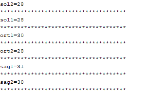
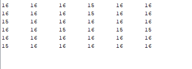
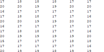
When I remove this part I see values like this:
This values all sensors on the white floor
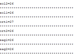
this values all sensors on the black line:
When i remove this part. There is a no significant change. I dont know why this reason ? I’ve been researching for a while but i couldnt find this reason.
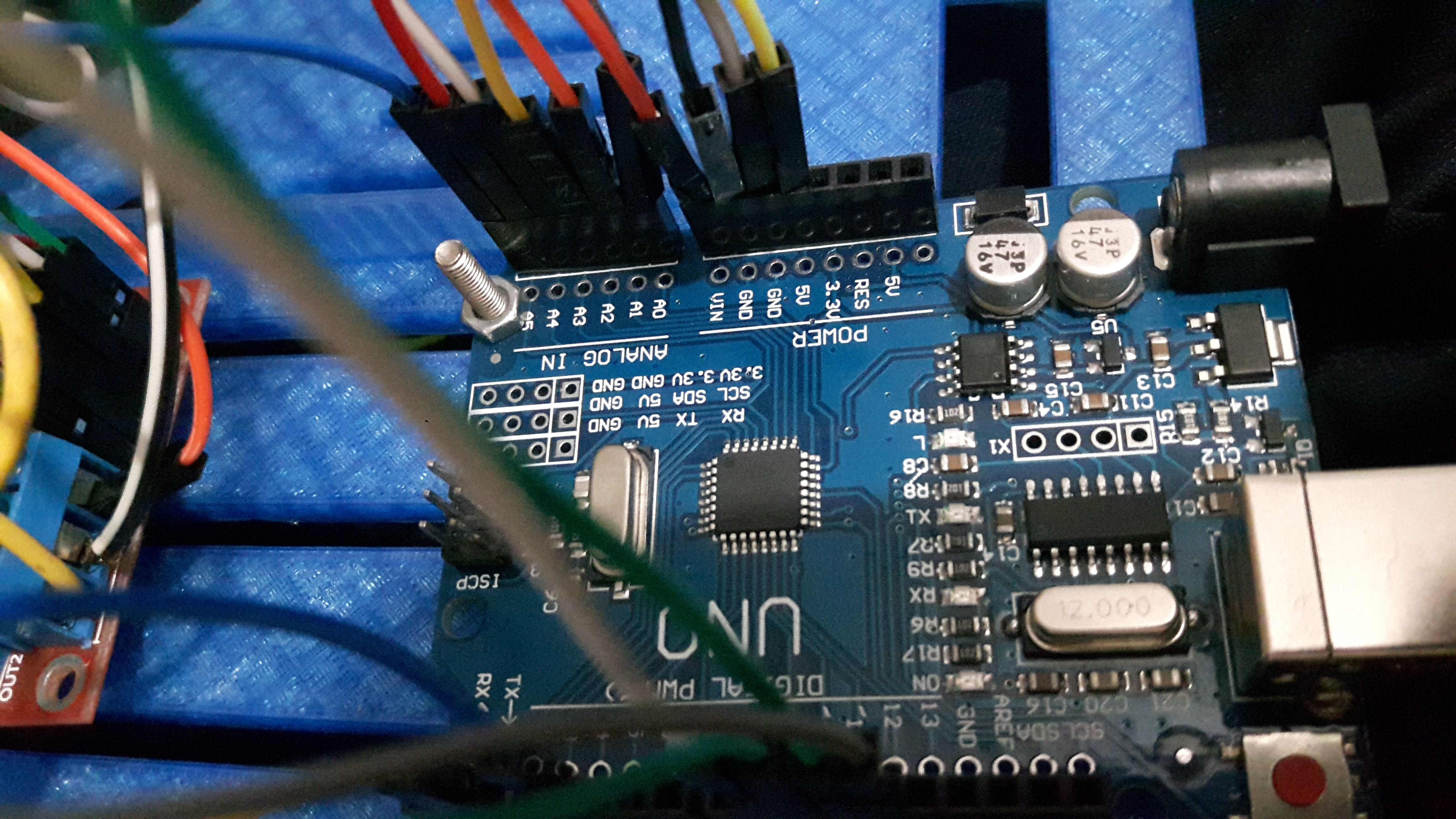
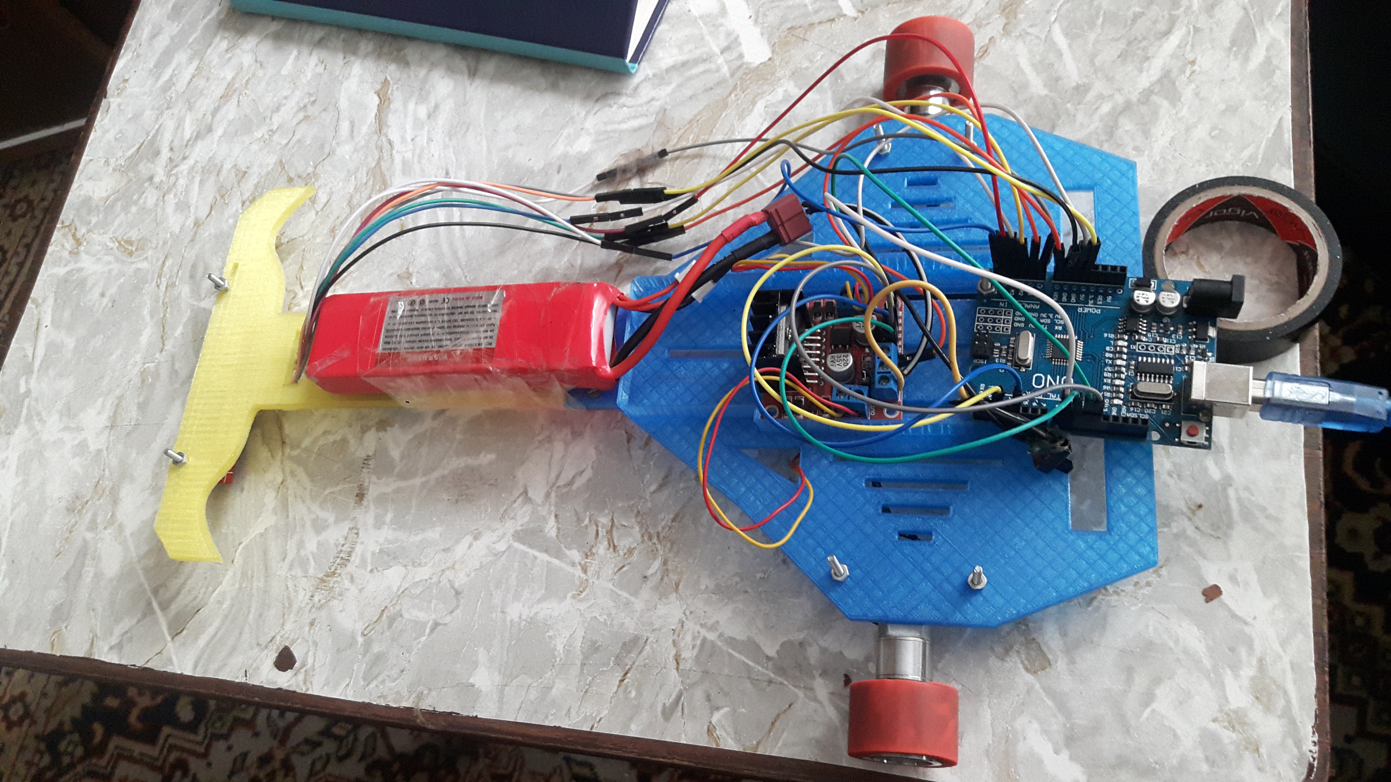
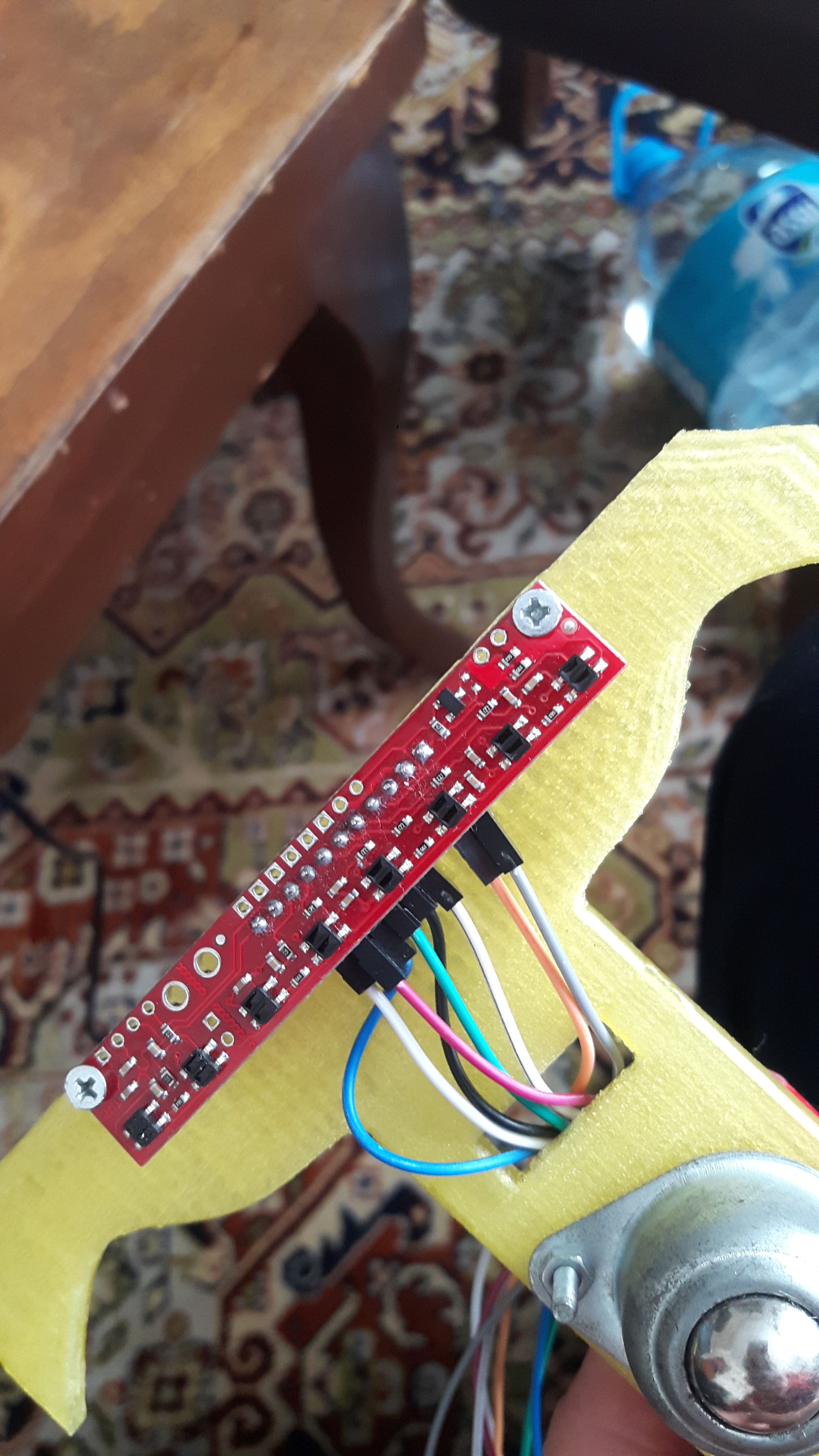
Which Arduino are you using? Can you send pictures that clearly show your array and its connections? Can you post the full sketch that you are running?
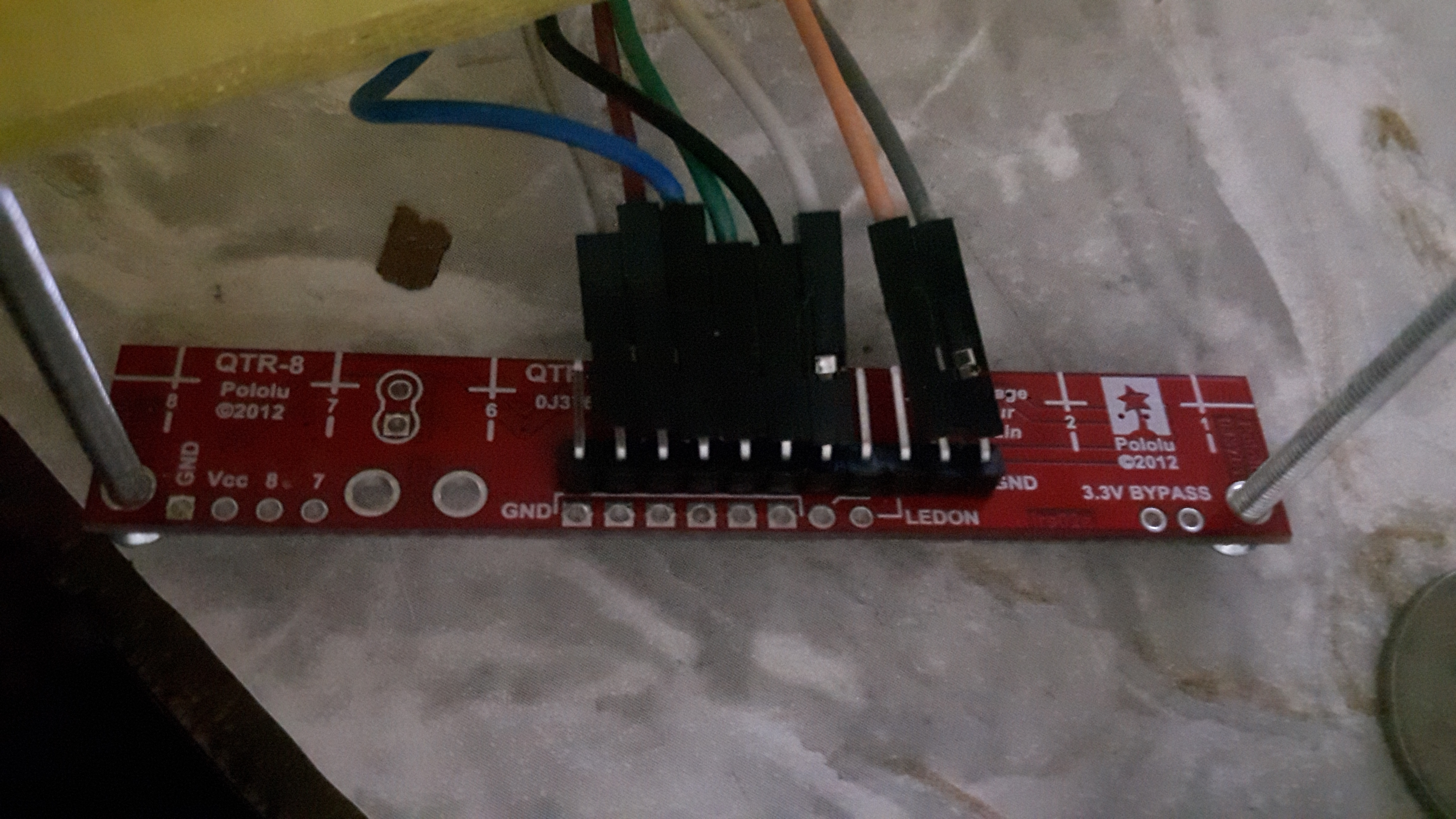
Can you try running the “QTRARawValuesExample” sketch from our Arduino library for the QTR sensors and tell me what values you get when detecting the black line and white surface? Can you also post pictures that clearly show the top of your QTR array?
Can you share pictures that clearly show the component-side of the array? (You posted a picture from the same angle.) Also, how are you supplying power to the array? From your pictures, it looks like you are connecting something to the 5V from your Arduino Uno, but it also looks like the wire color changes in between pictures. Also, the angle of the QTR header pins looks like it might be something like 45 degrees; did you bend those pins? Finally, can you share a sample of the raw output you are getting when running our sketch?
Yes you are right . Im supplying power with ardunio 5V Pin. and
The reason for the change of wire colors wire’s is not too long and i extended other wires for reach arduino’s pins and I bended headers.
as you see
Those latest readings show low voltages from the QTR sensors, which means either they are reading high reflectance (or otherwise high amounts of IR) all the time or that there could be power supply problems. Can you check your connections? In particular, can you remove power from the QTR array and use a multimeter to check for continuity between the sensor array and the Arduino at the VCC, GND, and signal pins and then supply power to the QTR array and measure the voltage at the array’s VCC pin?
Your initial message showed white background readings of ~90 and black line readings ~800, which is normal. Your second messages shows both white background readings and black line readings of ~30. This is abnormal and suggests either a wiring issue or you changed the program.
Using standard Arduino settings, you get 9600 ADC reads per sec (ADC conversion takes 13 ADC clock counts and the ADC clock is set at 125kHz). If you were reading just the ADC in your loop and were using 6 sensors like it appears you are, that would allow you to read the 6 sensors 1600 times a second. I believe that the Pololu library takes 4 readings per sensor before reporting it. So you are down to 400 readings of the complete set. Which would be capturing readings of the 6 sensors every 2.5 ms. This should be way sufficient for a simple line follower. The rest of your loop should take only a few ms or less. If you need more ADC conversion speed you can alter the 328P’s ADC clock registers to get more speed (see:http://forum.arduino.cc/index.php?topic=6549.0).
First you need to get your readings back to what you were seeing in your initial message.