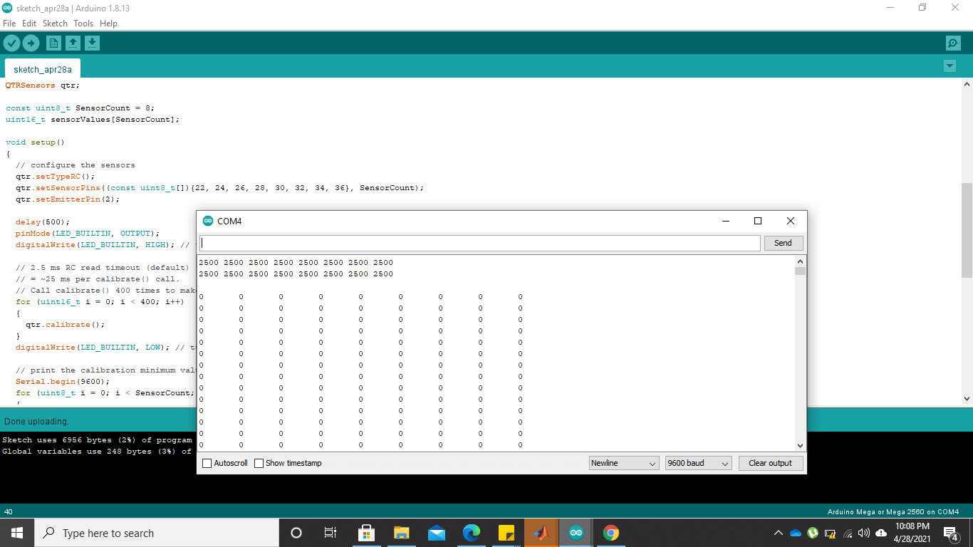
Hi people, I have read a lot of discussions here about this sensor and figured out a lot of problems. I have mounted the sensor on a robot to detect black lines on the surface. The current is that when I try to calibrate the sensor, the calibration
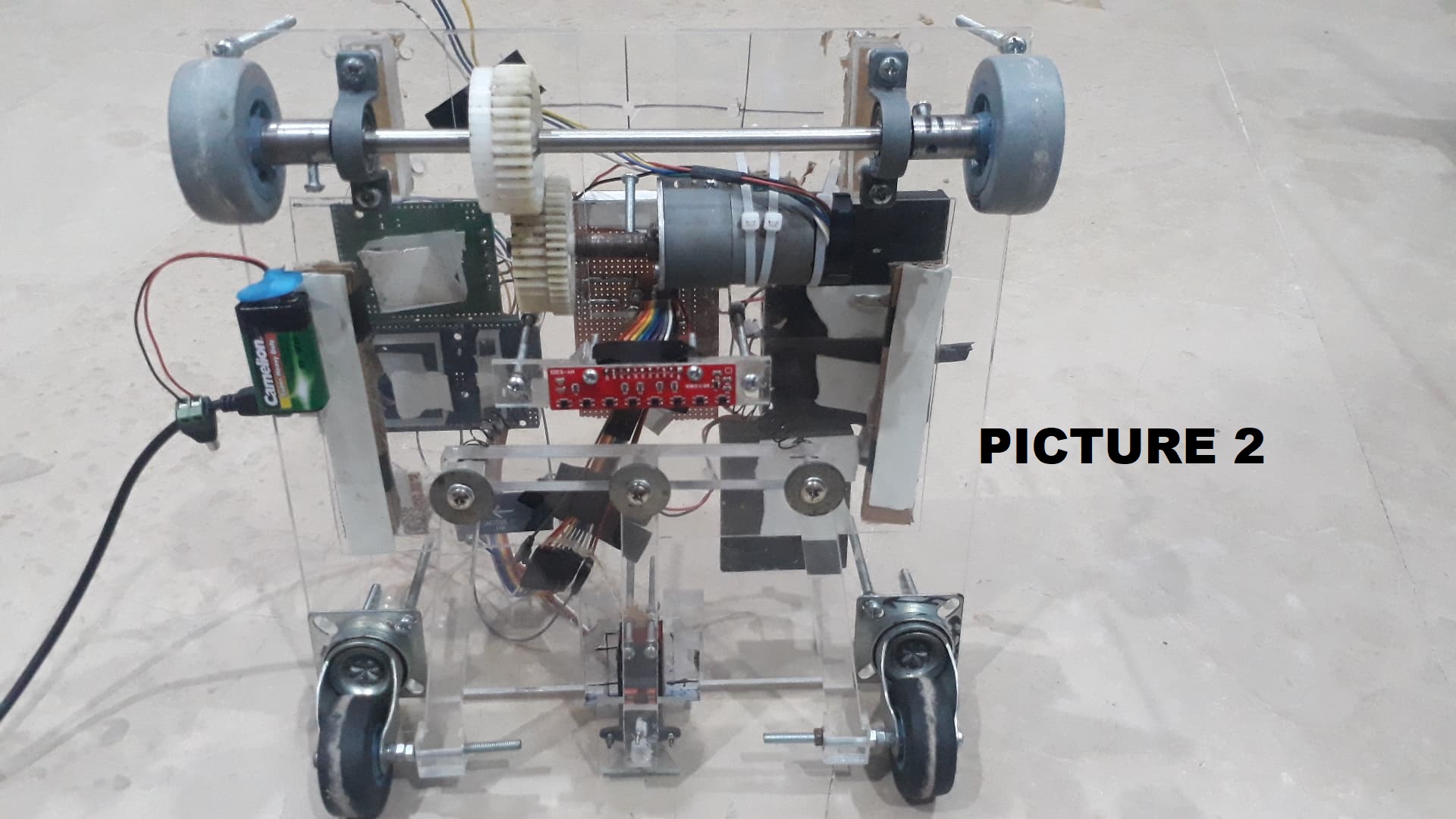
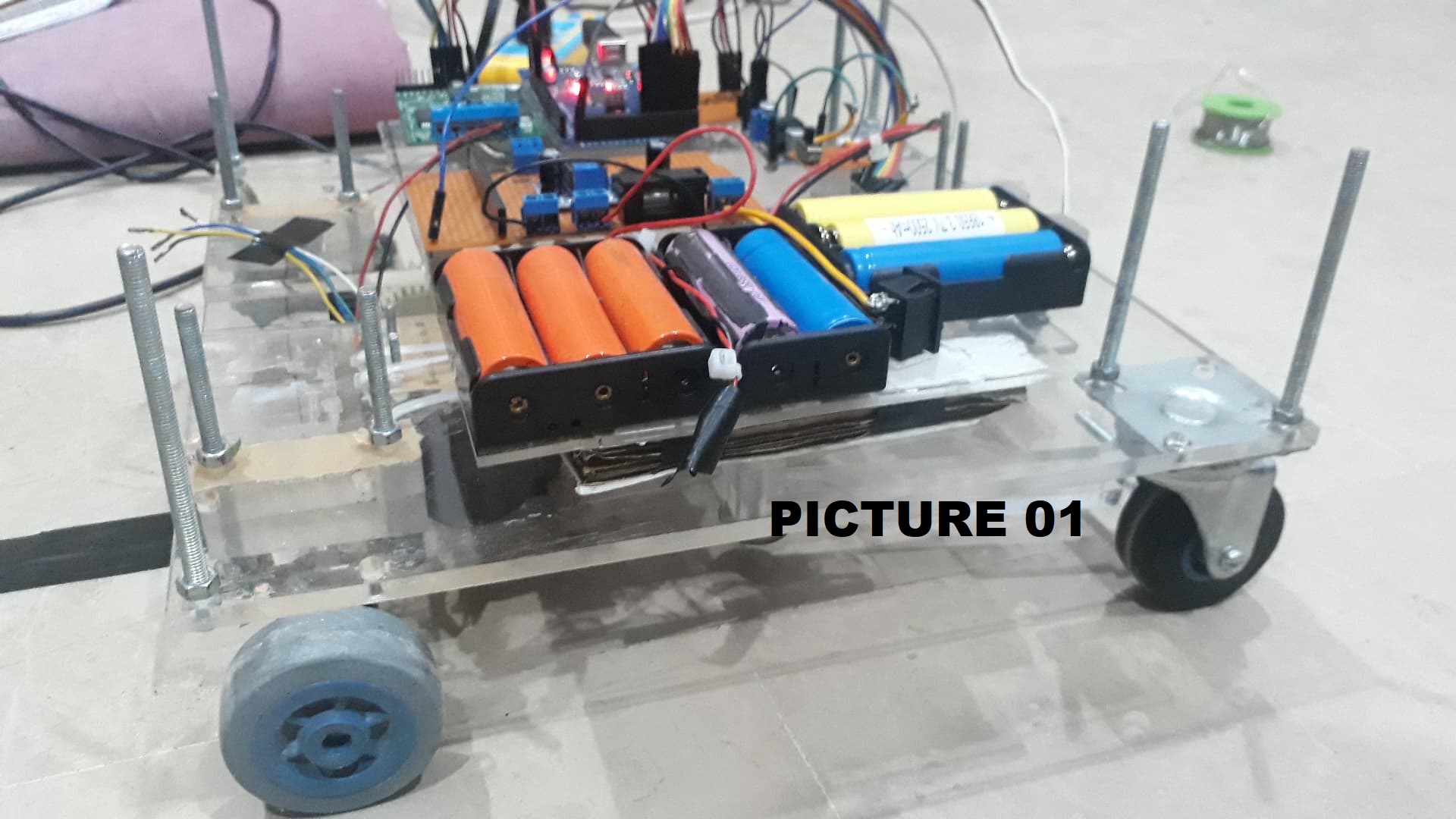
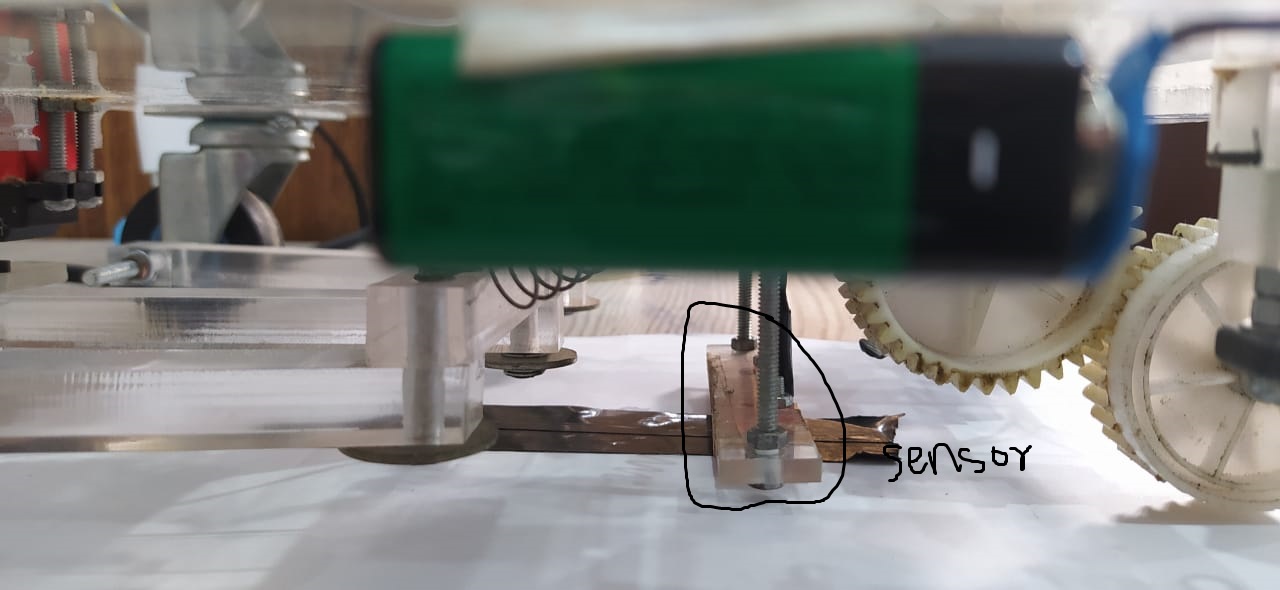
always returns 2500 for minimum and maximum reflectance. However, when I bring my robot to position 2 (refer to the images), and manually move a piece of paper across the sensor, it returns decent calibration and then also, detects the line on the paper as it supposed to. I speculate that in position 1, there are too many shadows which are causing problems in the sensor’s calibration. If so, then can someone tell me how to deal with this.
The sensors give a purple color to the camera, the voltage supplies and arduino wirings are right.
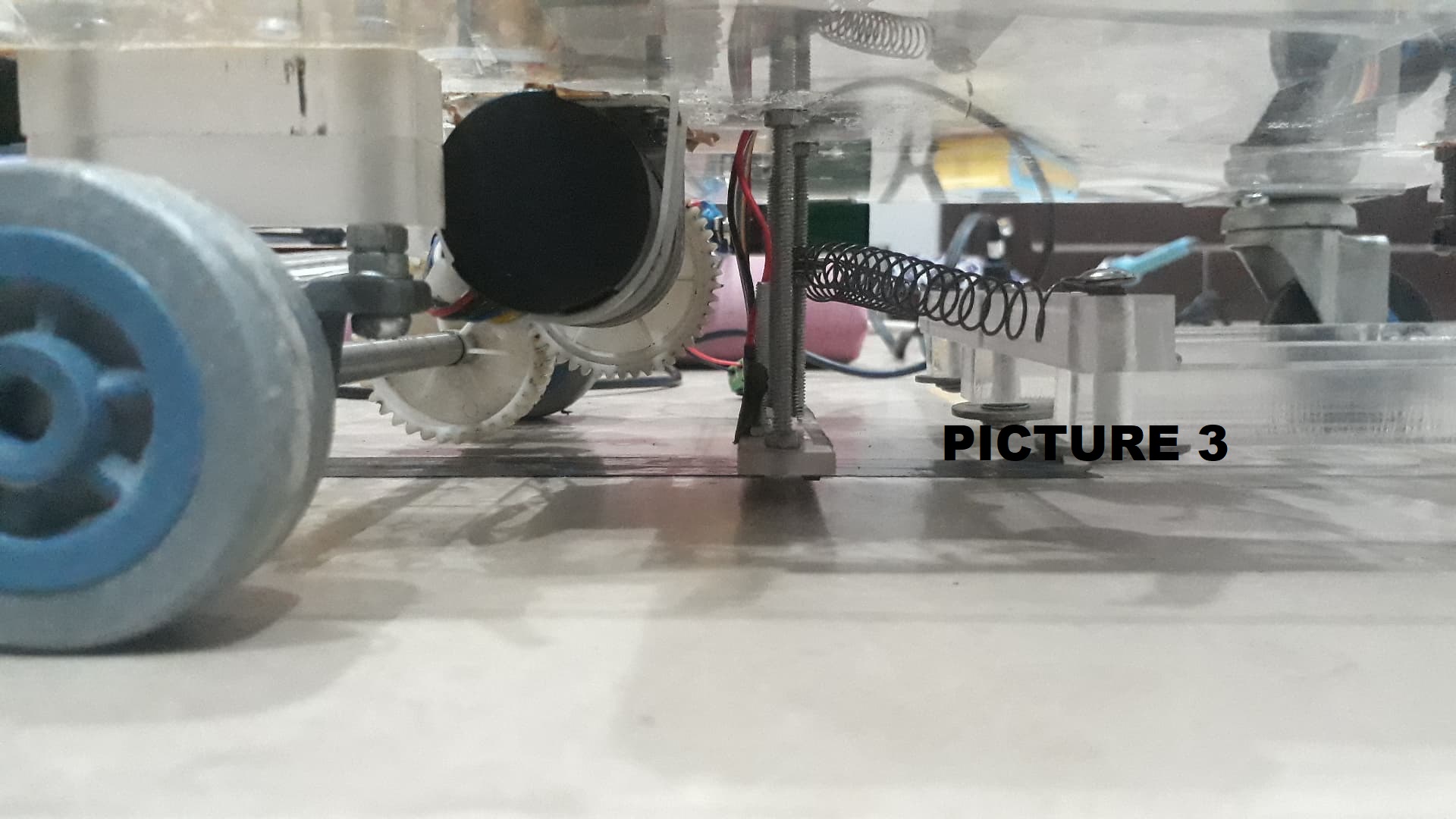
Readings of 2500 means not enough light is returning to the sensor. It is hard to tell from the picture, but it looks like the sensor might be too far from the surface when the robot is in position 1. As mentioned on our QTR-8RC product page, the optimal sensing distance is about 0.125" (3 mm).
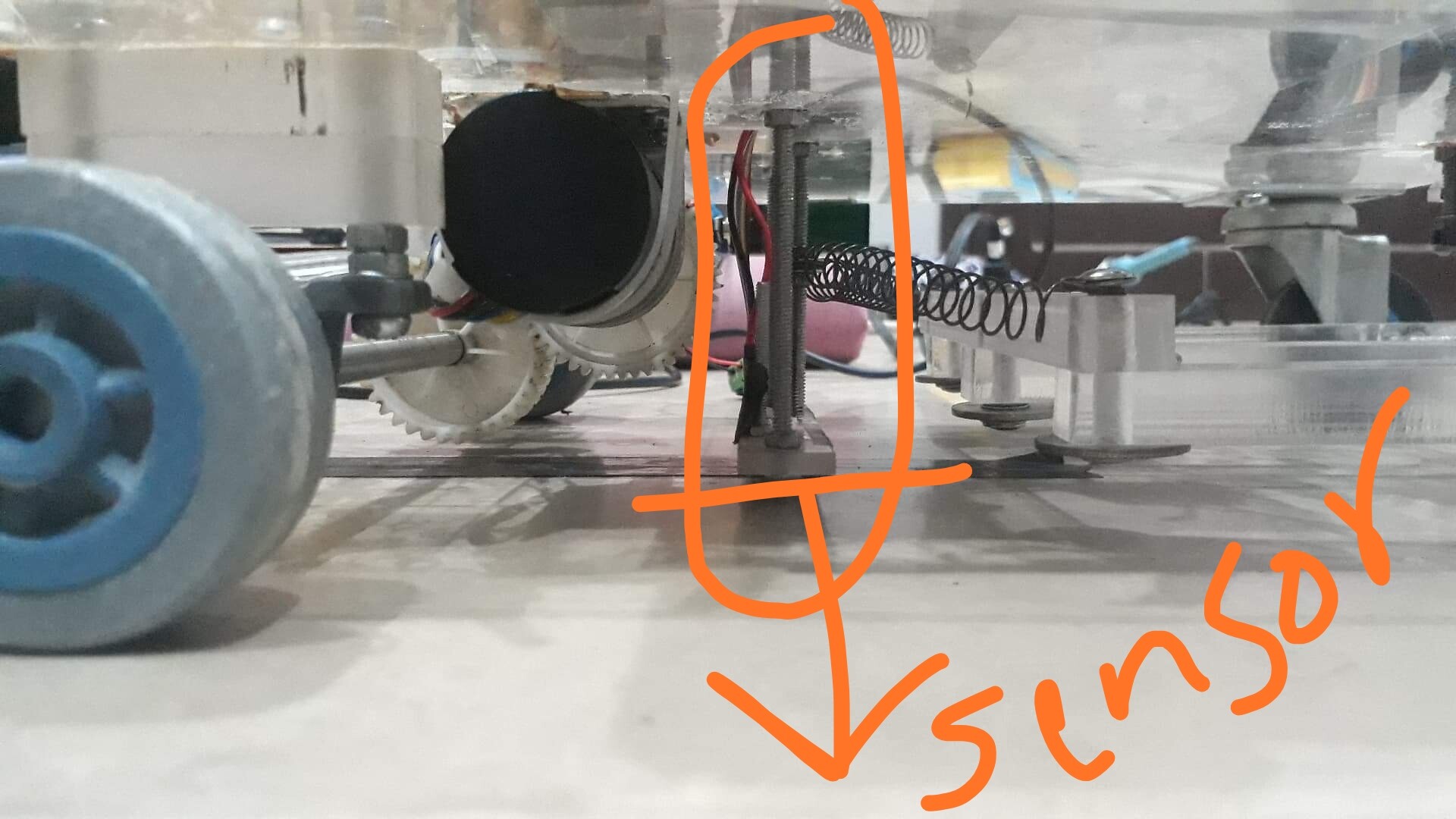
Hi Claire. Thank you for your reply. If you see picture 3, you can get an idea of how near the sensor is. I am adding it here again. I did measure it and it is about 3mm.
Can you elaborate on the affect of shadows on this sensors performance and readings.
That picture makes it much more clear. If you are using the emitters, I would expect shade or shadows like you have to help you get more consistent results from the sensor. (Florescent lights or sun light contain IR light that can throw off the sensor readings.) Do you have the emitters on? Could you try the QTRRCExample.ino from our library? It automatically calibrates for the first 10 seconds after the program is started; you should make sure each of the sensors pass over the line multiple times during this calibration period. More details are in the comments at the top of the code.
Hey claire, I was using the same code as you posted. I am getting these results. The only difference is the pin configeration i have used which you can see in the screenshot.
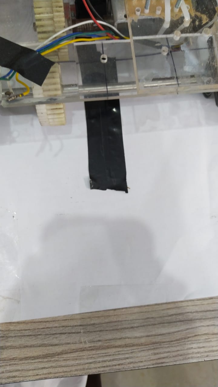
The sensor is super close to the surface. Attaching a picture for reference once again. I have also attached the picture of the line i am using to calibrate.
Can you tell me what do you mean by having the emitter’s own. I have used the camera technique to check the arrays. A purple light can be seen in all of the arrays from a camera lens.
Our QTR-8RC sensors have an emitter (IR LED) and detector(sensor). You can chose to use just the detector or both the emitter and detector. If you are seeing IR light from the sensors, the emitters are on.
The line you are using seems okay. Could you post a video showing how you are moving the robot while calibrating, in both position 1 and position 2? Could you also post the output you get from calibrating in position 2?