
Hi, I’m currently using QTR-8RC for my PD line follower robot. But unfortunately these sensors were now out of stock in my country. I’m planning to use the QTR-MD-08RC in case my old sensor needs replacement. I read that the sensor pitch of the new QTR-MD-08RC is 8mm while the older QTR-8RC is 9.5mm. Will there be any changes I should make in terms of the code or anything?
After we released the 2nd generation QTR sensors (the ones with black silkscreen like the QTR-MD-08RC you are interested in using), we also made changes to the structure of the QTR library. You will have to update your code to work with the new sensors, although the changes should be pretty minor.
-Jon
Will I still be able to use the QTR-8RC after the library update? And what changes particularly will I make in the code?
Yes, you can still use the older QTR sensors like the QTR-8RC with the updated library. To get a sense for what changes you will have to make, I recommend reading the description of the latest version, version 4.0.0, as well as the -RC examples. If something is not entirely clear or if you have a specific question about how to modify your code after reviewing that content, feel free to post here and I would be happy to help.
-Jon
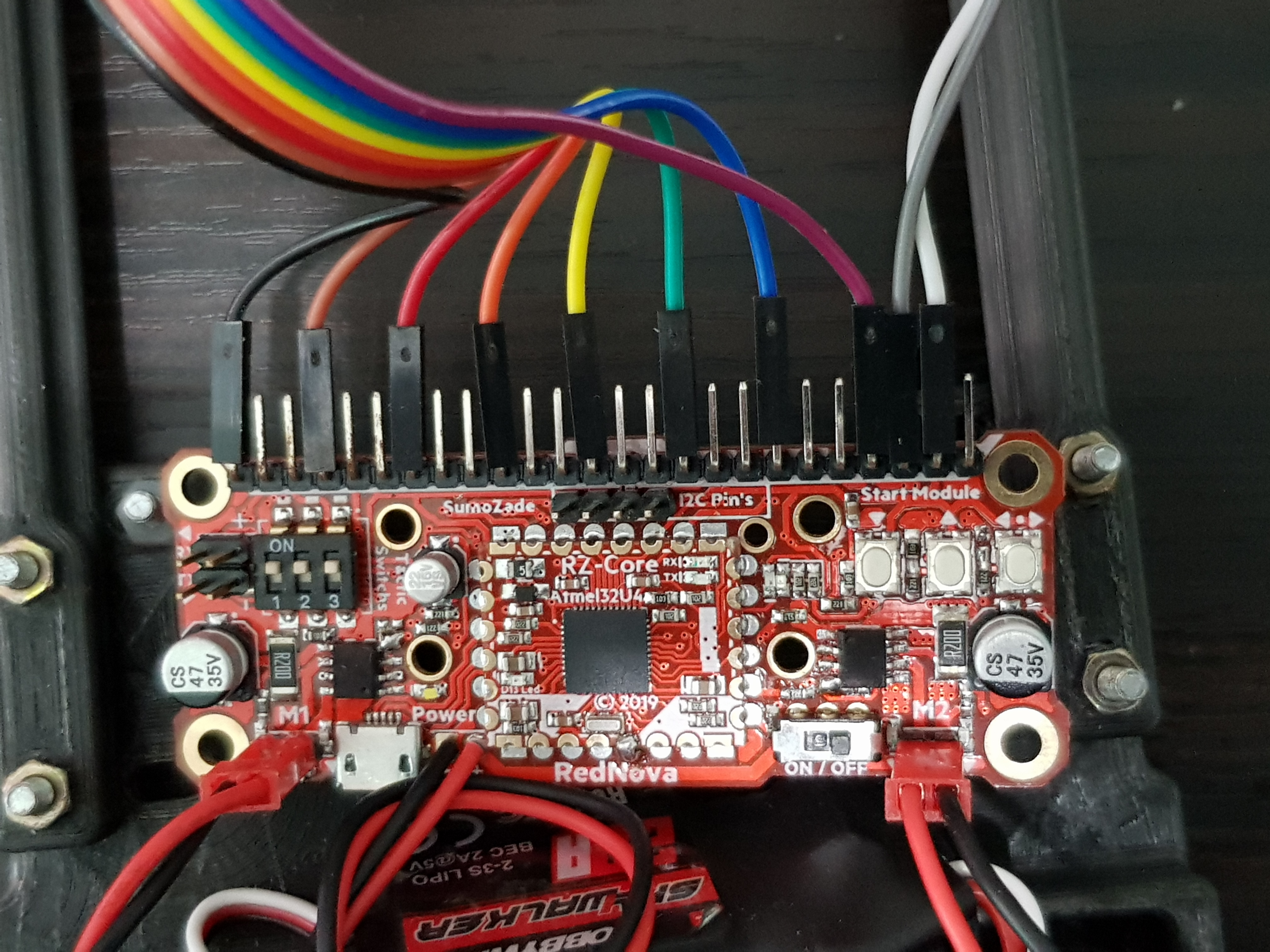
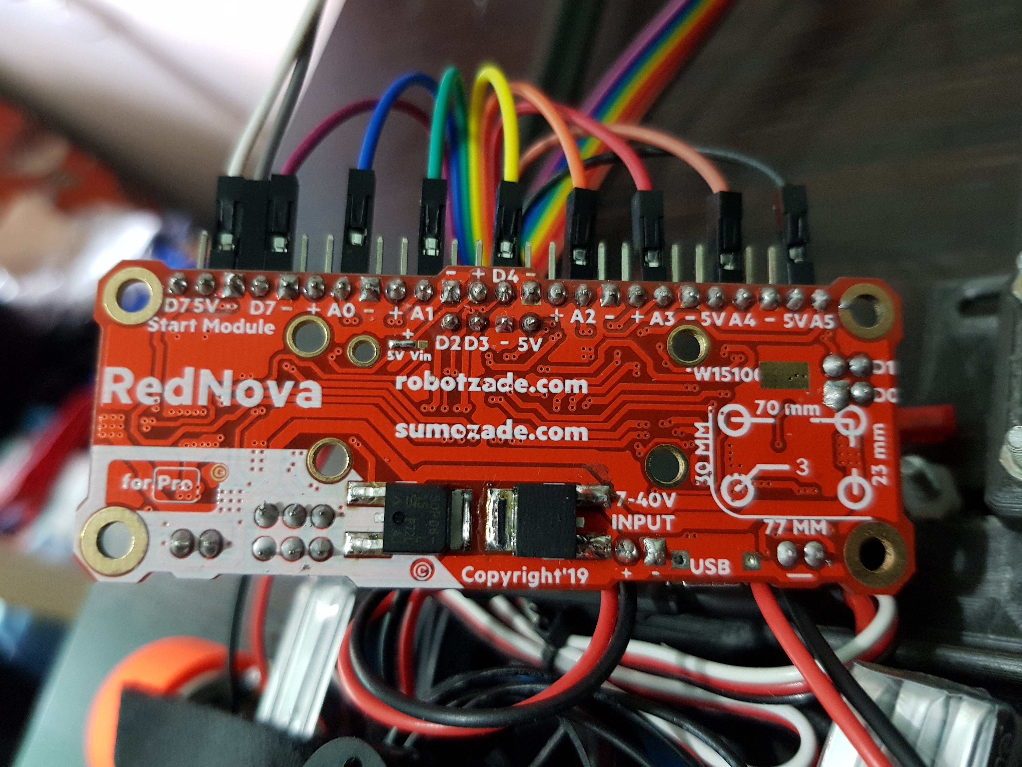
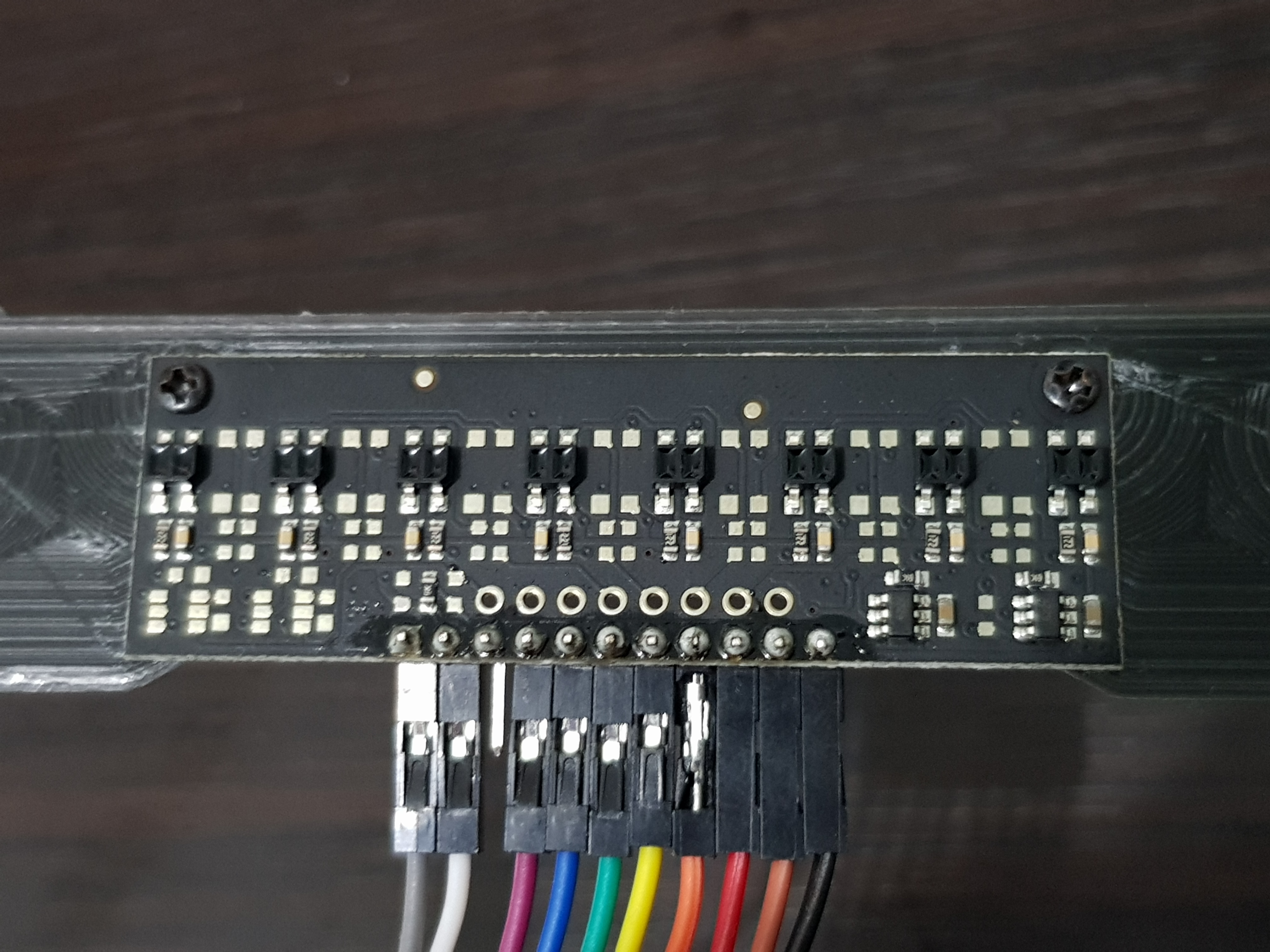
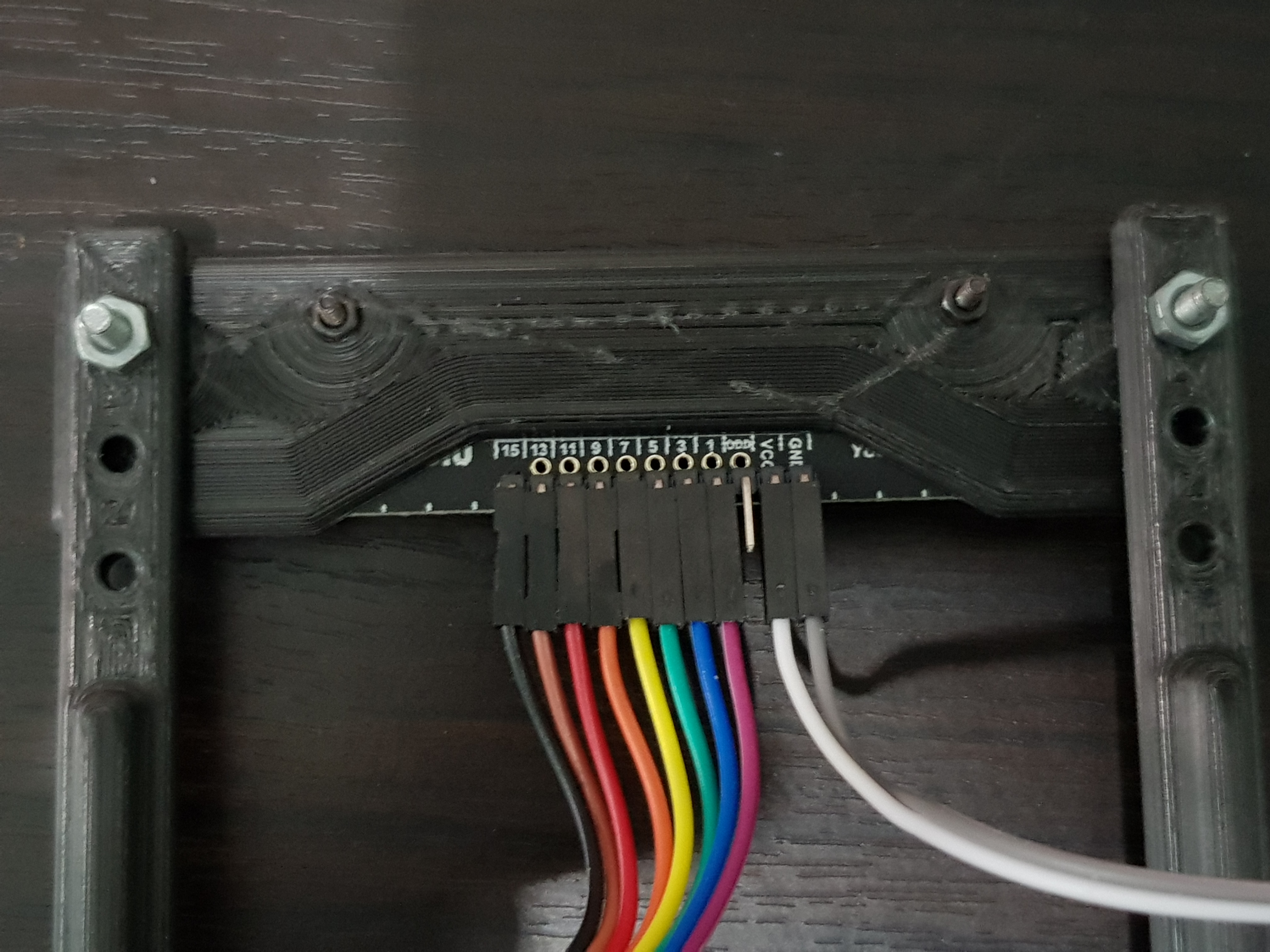
Hi, so I just got the QTR-MD-08RC. It’s connected to an Arduino Leonardo board. Everytime I disconnect it from the computer and turn it on, it doesn’t work. The whole arduino doesn’t work. But when I remove the Vcc and GND pins, the arduino board works. Also, when I connect it to the computer and try the sample code, (Vcc and GND is connected) it works. I did not connect the emitter pin btw.
And there are also no shorted connections. What can I do about this? Could it just be a broken QTR board I bought?
Hello,
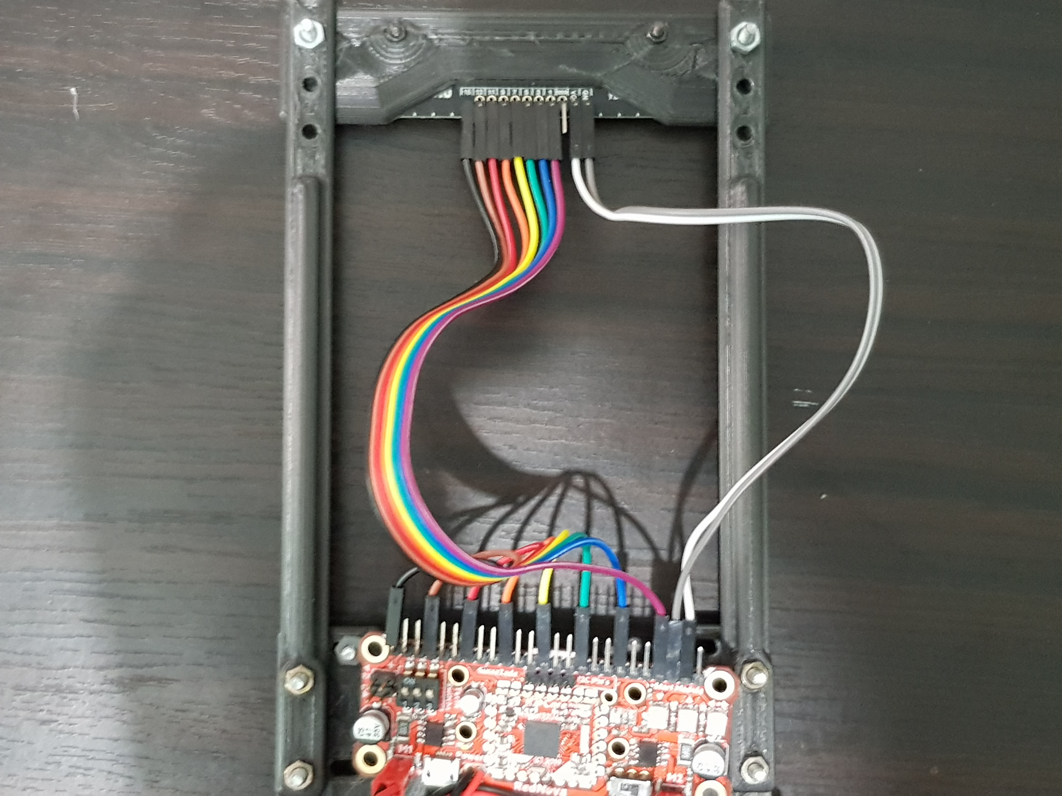
Can you post your code and some pictures of your setup that clearly show all connections?
-Derrill
#define sagtabanhiz 60
#define soltabanhiz 60
#define solmotoryon  10
#define solmotorpwmpin 9
#define sagmotoryon 5
#define sagmotorpwmpin 6

QTRSensors qtr;

const uint8_t SensorCount = 8;
uint16_t sensorValues[SensorCount];

void setup()
{

      // configure the sensors
      qtr.setTypeRC();
      qtr.setSensorPins((const uint8_t[]){2, A0, A1, 4, A2, A3, A4, A5}, SensorCount);
      qtr.setEmitterPin(2);


      delay(500);
      pinMode(sagmotoryon, OUTPUT);
      pinMode(sagmotorpwmpin, OUTPUT);
      pinMode(solmotoryon, OUTPUT);
      pinMode(solmotorpwmpin, OUTPUT);

      delay(500);
      pinMode(LED_BUILTIN, OUTPUT);
      digitalWrite(LED_BUILTIN, HIGH); // turn on Arduino's LED to indicate we are in calibration mode

     for (uint16_t i = 0; i < 400; i++)
     {
         //if ( 0 <= i && i < 5   )  hafifsagadon();
         //if ( 5 <= i && i  < 15   )  hafifsoladon();
         //if ( 15 <= i && i < 25   )  hafifsagadon();
         //if ( 25 <= i && i < 35   )  hafifsoladon();
         //if ( 35 <= i && i < 45   )  hafifsagadon();
         //if ( 45 <= i && i < 55  )  hafifsoladon();
         //if ( 55 <= i && i < 65   )  hafifsagadon();
         //if ( 65 <= i && i < 75  )  hafifsoladon();
         //if ( 75 <= i && i < 85   )  hafifsagadon();
         //if ( 85 <= i && i < 90  )  hafifsoladon();

         //if ( i >= 90  )  {frenle(); delay(5);}

       qtr.calibrate();
       delay(4);
      }
    digitalWrite(LED_BUILTIN, LOW); // turn off Arduino's LED to indicate we are through with calibration
    Serial.begin(9600);
    delay(2000);
}

int sonhata = 0;
float Kp = 0.04;
float Kd = 0.8;

int sagmotorpwm = 0;
int solmotorpwm = 0;
int zemin=0;

void loop()
{

  // Pozisyon hesabı QTRlibrary tarafından yaptırılıyor
  uint16_t sensorValues[8];
  uint16_t position = qtr.readLineBlack(sensorValues);
 // unsigned int position = qtrrc.readLine(sensorValues,1,zemin);
  int hata = position-3500;

  // zemin değiştirme kodları
 // if ( sensorValues[0]<200 && sensorValues[7]<200  ) { zemin=0;  }//beyaz
 // if ( sensorValues[0]>750 && sensorValues[7]>750  ) { zemin=1;  }//siyah


  //////////// motorlara verilecek hız düzeltme oran hesabı
  int duzeltmehizi = Kp * hata + Kd*(hata - sonhata);
  sonhata = hata;


  //////////// Motorlara uygulanacak kesin hız ayarları
   sagmotorpwm = sagtabanhiz + duzeltmehizi  ;
   solmotorpwm = soltabanhiz - duzeltmehizi  ;

   sagmotorpwm = constrain(sagmotorpwm, -255, 255); ///// Burada motorlara uygulanacak PWM değerlerine sınırlandırma getirilmiştir.
   solmotorpwm = constrain(solmotorpwm, -255, 255);
   motorkontrol(sagmotorpwm,solmotorpwm);
  //   Seri monitörde hata, sağ ve sol motor hız değerlerini gösternek için alttaki satırı aktif yapınız
    // Serial.print(hata);  Serial.print(" "); Serial.print(sagmotorpwm); Serial.print(" "); Serial.println(solmotorpwm); delay(100);

}
// Motor kontrol alt programı
void motorkontrol(int sagmotorpwm, int solmotorpwm){

  if(sagmotorpwm<=0) {
      sagmotorpwm=abs(sagmotorpwm);
      analogWrite(sagmotoryon, LOW);
      analogWrite(sagmotorpwmpin, sagmotorpwm);
    }
  else {
      analogWrite(sagmotoryon, sagmotorpwm);
      analogWrite(sagmotorpwmpin, LOW);
  }

  if(solmotorpwm<=0) {
     solmotorpwm=abs(solmotorpwm);
     analogWrite(solmotoryon, LOW);
     analogWrite(solmotorpwmpin, solmotorpwm);
    }
   else {
    analogWrite(solmotoryon, solmotorpwm);
    analogWrite(solmotorpwmpin, LOW);
   }
}


void frenle(){motorkontrol(0,0);}

void hafifsagadon(){motorkontrol(0,0);}

void hafifsoladon(){motorkontrol(0,0);}
From the description of the behavior you are getting, this seems like it could be a power issue. In particular, it sounds like your microcontroller can provide more power to VCC when connected over USB than when powered externally, and that the amount of power the QTR sensor board needs is somewhere in between. Your pictures show a white and gray wire connecting the QTR board to your microcontroller. Is this how the QTR sensor was powered when your Arduino was disconnected from your computer? Does the QTR sensor work with your microcontroller when you connect an external supply to VCC on the QTR?
-Jon
Yes that’s the how I power the QTR. It works when I connect it to other 5v supply.
Is this happening because the QTR-MD-08RC consumes more power than the QTR-8RC? If so, how can I lower the current consumption? The microcontroller is working fine with the old QTR.
It is possible your system is behaving that way because the newer QTR-MD-08RC draws more current than the old QTR-8RC. The QTR-MD-08RC can draw up to 125mA with all LEDs on at max brightness while the QTR-8RC has a total board current consumption of just under 100mA (also with all LEDs on at max brightness).
You can reduce the amount of current drawn by new QTR sensors like the QTR-MD-08RC by turning their emitters off some (or most) of the time. You can do this by driving or pulsing the appropriate CTRL pin(s) low. For the QTR-MD-08RC, you should send those signals to the CTRL ODD pin. I recommend reading the “Interfacing with the outputs of the RC versions” and “Emitter control” sections of the QTR-MD-08RC product page before making any changes to your system.
-Jon