QTR-8RC reflectance sensor (with Arduino Duemilanove)

Hello
I have a QTR 8RC Reflectanse sensor and am struggling to get the values of reading them …

I have the following code:

#include <PololuQTRSensors.h>
PololuQTRSensorsRC qtr((unsigned char[]) {9, 8, 7,6,5,4,3,2}, 8);

void setup(){
  Serial.begin(9600);
  for (int i = 0; i < 250; i++){
    qtr.calibrate();
    delay(20);
  }
}

void loop()
{
  unsigned int sensors[8];
  int position = qtr.readLine(sensors);
  int error = position - 1000;
  Serial.println (position);
  delay(50);
}

and I can not get any value from these sensors: /, can you help me?

anyone can give me an answer on my code? or even leave a code that allows you to do what I want?

thank you for understanding.

Hello.

From your code it looks like you are trying to read the sensors using an Arduino, but you really should include this crucial information in your post. What specific board are you trying to program?

- Ben

yes, I am trying to read the values from the Arduino,
I’ve seen post’s with the same problem I have here in the forum, however this problem who had stopped responding and I got no replies … here, contain 2 codes, both do not work …

be that you could suggest me a Alternatia code (for use with 8 sensors) that allows me to read the value of the sensors?
Thanks

What Arduino board are you using?

arduino duemilanove…
If you can not work with these sensors will have to buy some sensors IV “normal” and change the way I do the follower of lines. I enjoyed using this array of sensors, but gonna need help, because I can not even get a value of reading them …

if you can help me thanks a lot …

I’ll do some tests today with an Arduino to see if I can figure out what might be going wrong. I’ll let you know what I find.

- Ben

ok, thank you for the help Ben.
I am waiting for your response …

Fred,

I have tested a QTR-1RC sensor with an Arduino Duemilanove; everything worked as expected. Can you try the following test:

  1. Connect VCC and GND on your QTR-8RC sensor to 5V and GND on your Arduino, respectively. Leave LEDON disconnected.
  2. Connect sensor output 1 to digital pin 3 on your Arduino.
  3. Run the following sketch:
#include <PololuQTRSensors.h>

PololuQTRSensorsRC qtr((unsigned char[]) {3}, 1);

void setup()
{
  Serial.begin(9600);
}

void loop()
{
  unsigned int readings[8];
  qtr.read(readings);
  Serial.println(readings[0]);
  delay(1000);
}

When I do this (using the Arduino 0018 IDE), as I bring my finger close to sensor 1 and then away again, I get the following output in the serial monitor window:

4000
4000
4000
1321
601
226
271
604
1029
1512
2934
3579
4000
4000
4000

What results do you get when you try this?

- Ben

I always get the value 4000: /
from time to time the value changed, but I do not know pq, poque get to a point that if I contiue to hold the finger sensor and get the value or ariava (it was always 4000) …
tried on and off the LED and the result was the same …

can you help me?

What version of the Arduino software are you using? Can you post a picture of your setup? Also, can you verify that the LEDs on your sensor are on? One way to do this is to look at the sensor through the display of a cheap digital camera, such as a cell phone. Such cameras lack IR filters, so you can use them to see IR light sources. For example, notice how the point-and-shoot camera in the picture below shows the IR LEDs of our IR beacon shining (in purple) but the DSLR with which the picture is taken does not show the LEDs:

One other thing you can try is holding the QTR sensor so that it is facing direct sunlight. Do you see the number change from 4000 to something smaller if you do this?

- Ben

Welcome Ben.
I can not change the núemro of 4000 to any other …
I think I am connecting everything correctly …
pins on the left side is staked because I feed the sensor with 3.3volts (a food with 5 or 3.3 the value never goes out of 4000), you know why?

let down as I have pictures of the connections made …
Thanks

img442.imageshack.us/i/dsc09327.jpg/
img339.imageshack.us/i/dsc09331.jpg/
img168.imageshack.us/i/dsc09328r.jpg/

Fred,

Those first two pictures are somewhat blurry, but it looks to me like you haven’t actually soldered the pins into the sensor board. Is this correct? If so, this is probably why you aren’t getting any signals from the sensor (just letting header pins press loosely against the through-holes makes for terrible electrical connections).

Also, pretty much all of your connections look wrong to me. In your first picture it looks like you are connecting VCC to power through a resistor? Furthermore, you are using a double-row header with a breadboard, which is shorting together the pins of the two rows. Sensor outputs 3-8 are being shorted to ground through the breadboard while sensor output 2 is being shorted to power and sensor output 1 is being shorted to LEDON. In general, it looks like you’re trying to make things very complicated without understanding what you’re doing. For example, why are you running the sensor at 3.3V rather than using the 5V output of the Arduino?

If you want to use the sensor in a breadboard, please do the following:

  1. SOLDER a 1x11 header strip into the sensor board at the location marked by the long yellow rectangle in the picture below:

This 1x11 strip gives you access to all of the sensor’s pins; you do not need to use the lower 8 pads (below the yellow rectangle) if you use the upper 11 (in the yellow rectangle).

  1. Do NOT short the 3.3V bypass pins together.
  2. Connect the 5V output of the Arduino DIRECTLY to VCC on the sensor board (do not connect it through a resistor).
  3. Leave the LEDON pin disconnected. The IR LEDs should still be on with this pin disconnected (verify this with your camera).
  4. Connect sensor output pin 1 DIRECTLY to Arduino digital pin 3 and run the sketch I previously posted.

If things still aren’t working at this point, please post new pictures of your setup. Try to make them as clean and understandable as possible, and include the Arduino in the pictures this time, too.

- Ben

iiiii
now works, when you put something black on the sensors they give the value 4000, do not know how such a mistake, it was the short circuit: /

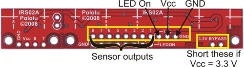
as a code for to use with sensors, I visualized this link here:

pololu.com/docs/0J19/3

just do not understand how the error can always varies between -1000 and 1000, as the motor speed will vary so?,

can you explain me? and if possible exemplify me a code to use with this array of sensors? (to make the follower of lines).

What I want is for the engines to turn the two maxima velocidadequando sensors are about half the black line (00011000, thus exemplifying the best), and that when this state is established: 00110000 engine right little slow, but when check this: 11000000, the right engine very slow, you know? …

I worked out the following schedule:

/*Bibliotecas necessárias*/

#include <Servo.h> 

/*variáveis de configuração*/
int nsensores = 8;
int rmotor = 9;//pino do motor direito (PWM);
int lmotor = 10;//pino do motor esquerdo (PWM);
int sensor[] = {8,7,6,5,4,3,2,1};


/* variaveis auxiliares*/
int senval[]= {0,0,0,0,0,0,0,0};//variavel onde será guardado os valores dos sensores.
int Rtarguetval = 0;// valor pretendido para o motor direito.
int Ltarguetval = 0;// valor pretendido para o motor esquerdo.
int nowvalR = 0; //valor actual do motor direito.
int nowvalL = 0;//valor actual do motor esquerdo.
int vel_max = 130;//velocidade máxima dos motores.
int CStop = 0;//
boolean stop = false;
double LineErrorVal = 0.0; 


void setup(){
  Serial.begin(9600);
  pinMode (rmotor, OUTPUT);
  pinMode (lmotor, OUTPUT);
  DDRD = LOW;// portas 7..0 como inputs, aqui ligarei os 8 sensores.
}

void loop(){
  stop = false;
  //Lemos os valores dos sensores
  readALLSensores();
  if(senval[11111111]){
    stop = true;
  }
  //vemos se estes valores se mantêm, duante 30ms
  if(stop){
    CStop++;
    if (CStop >=30){
      Rtarguetval = 0;
      Ltarguetval = 0;
    }
    else{
      stop = false;
    }
  }
  //De seguida iremos determinar as velocidades para os motores, consoante o erro.
  if(LineErrorVal < 0.0){
    Ltarguetval = (int)(vel_max*(1-fabs(LineErrorVal)));
    Rtarguetval = vel_max;
  }else if (LineErrorVal > 0.0){
    Ltarguetval = vel_max;
    Rtarguetval = (int)(vel_max*(1-LineErrorVal));
  }else{
    Ltarguetval = (int)(vel_max);
    Rtarguetval = (int)(vel_max);
  }
  //controlar os arranques e travagens dos motors.
  if(Rtarguetval > nowvalR){
    nowvalL +=1;
  }else if (Rtarguetval < nowvalR){
    nowvalL -=1;
  }
  if (Ltarguetval > nowvalL){
    nowvalL +=1;
  }else if(Ltarguetval < nowvalL){
    nowvalL -=1;
  }
  
  // ter a certeza que a velocidade dos motores nao ultrapassam o valor desejado
  if (nowvalL > vel_max){
    nowvalL = vel_max;
  }
  if (nowvalR > vel_max){
    nowvalR = vel_max;
    delay(20);
  }
}
//FUNÇÔES//

void readALLSensores(){
  
    for(int i = 0; i < 8; i++)
  {
    senval[i] = digitalRead (sensor[i]);
  }
}
int bestSensor(int sensor[]){
  
  int bestSensor = 0;
  for (int i=0; i < 8; i++)
  {
    if (sensor[i] == 1){
      digitalRead (sensor[i]+1);
      if (sensor[i] +1 == 0){
        bestSensor = i;
      }
    }
    else if(sensor[i] == 0){
      digitalRead (sensor[i]+1);
      if(sensor[i] +1 ==1){
          bestSensor = i;
      }
    }
  }
}
//retorna valores entre -1.0 e 1.0, consoante o erro da linha
// se a linha estiver ao centro, o erro é 0.0.
double lineError (int sensor[])
{
  int best = bestSensor (sensor);
 
  double error = 0.0;
  
  // começando!!
  
  if (best == 3 || best ==4){
    error = 0.0;
  }
  else{ if(best == 2){
    error = -0.3;
  }
  else{if (best = 1){
    error = -0.6;
  }
  else{if (best = 0){
    error = -1.0;
  }
  else{if (best = 5){
    error =0.3;
  }
  else{if (best = 6){
    error = 0.6;
  }
  else{if (best = 7){
    error = 1.0;
  }
  {
    return error;
  }
  }
  }
  }
  }
  }
  }
}

but is for use with an array of 5 sensors “normal” with these sensors do not know and do heide, when you look at my schedule, my error ranges (-1 to 1) and this error as the engine speed will vary (try to look and realize I do not know how to explain), to use these sensors, percegi the error or is it 1000 or -1000, never varies in these numbers, hence my question …

could you me illustrate a simple code to “adapt” this array of sensors to the follower of lines?

thanks.

Fred,

I don’t really understand what you’re asking me. The page you linked to explains in detail how to use the sensors to read a line and adjust motors accordingly. What specifically about that page do you not understand?

- Ben

for example, here: int motorSpeed = KP * error + KD * (error - lastError);
23. lastError = error; , I do not understand what is the KP and KD, if I put this code in the compiler, which he will tell me is this, who does not know what these variables.

else, too don´t undersant as the error is calculated automatically,can you explain me this?

appreciate the help …

Did you actually read the page you linked to? Before the code it says:

And in the code itself, right above the lines you quoted is the comment:

If you want to understand how the error is calculated, read the documentation of the PololuQTRSensors::readLine() function in the QTR sensor library command reference. This documentation gives you the function used to compute a single value for the error using the sensor values. If you want even more details about how it works, you can take a look at the source code, which is in included with the Pololu AVR library download. The files with the QTR sensor library code should be in arduino-0018/libraries/PololuQTRSensors/.

Understanding how the error is calculated isn’t really all that important as long as it provides a value that can be used for PID. Just think of it as a sensor that tells you where the line is; you don’t need to know how it knows where the line is, you only need to know how to use that data for your application. Also, you’re welcome to write your own code for computing the error from the sensor values.

- Ben

I did the following code:

#include <PololuQTRSensors.h>  

PololuQTRSensorsRC qtr((unsigned char[]) {9,8,7,6,5,4,3,2}, 8);

void setup(){
  
  int i;
  for (i = 0; i < 250; i++)
  {
    qtr.calibrate();
    delay(20);
  }
}

void loop(){
  unsigned int sensors [8];
  int position = qtr.readLine (sensors);
  Serial.print (position);
  delay(500);
  
  if(sensors[3] > 750 && sensors[4] > 750)
  {
    return;
  }
  
  int error = position -1000;
  int lastError = 0;
  int maxspeed = 130;
  double KP = 0.1;
  int KD = 5;
  int motorspeed = KP * error + KD * (error - lastError);
  lastError = error;
}

but still have some doubts …

here: “if(sensors[3] > 750 && sensors[4] > 750)”

what I think is to do here is put my state of the robot It is ideal for example (I’ll put a logical 1 on the sensor that you are seeing black, white and 0 in order to be more explicit) I just want the two sensors to see through the black line, and then this error is 0, so: 00,011,000, or do I want my error is zero when you have the following status: 00111100, for example, I understand that this function put “my ideal state” of the sensors on both engines, the maximum walking speed, is it?

Ps: in my case I want to state It is ideal that is: 00011000. if wrong, you correct me please?

and within the void loop () (, put you can help me complete the code please? not know now how I like turning the engine on the left or right depending on the mistake …

I apologize for encomodo, if you can help me with the code thanks, so tomorrow could test the already barely-school …

thanks.

Hello,

Even if you are in the “ideal” state, you should still set your motor speeds. The section of code you included is not very useful.

As for setting the motor speeds, we can’t help you with that since we do not know how you are controlling your motors.

-Paul

I set the speeds of 130.
the calculation of the error will do that, I set the engine speed depending on the error by using the formula: KP + KD * error * (error - lastError), provided by you.

I intend to do is when I have been 00011000 both engines spin at 130, but if 00,110,000 of the right engine will slow down a bit, and if you have: 11000000 right motor slows down too much, or that’s what the error will do, right? … (you can see the code that I posted I anteriorente to a “normal sensors” that is pretty explicit there …

this library but I do not know how to use it well, then ask for your help,
I did the code I posted previously, but now I do not know how to put the engines on that floor with code, and walking because of the error, you can help me in this regard? if I podesses display examples of code or even add it the code posted by me … thanks