The 7th & 8th sensors does not seems to behave properly. When I block the 8th sensor, it effect the 7th sensor reading and blocking the 7th alone shows about 900+ more values than other blocked sensors.
Can you try blocking the sensor with some black electrical tape and testing it again over a white surface (like a piece of paper) to see if you get better results?
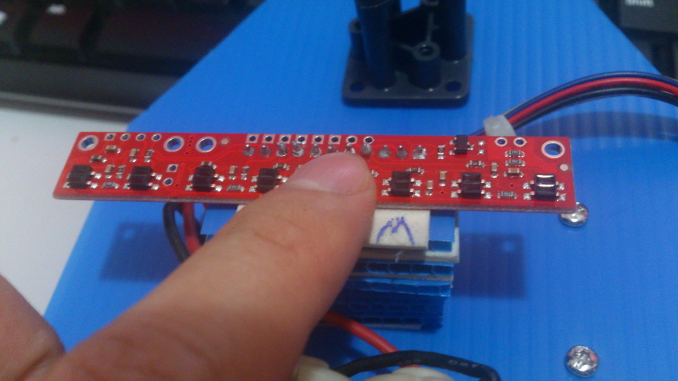
Sensor 1-6 are connected to analog pin A0-A5 and sensor 7 & 8 are connected to digital pin 11 & 12. I’ve tried connecting all 8 sensors to digital but the problem still remain the same.
#include <QTRSensors.h>

#define KP .4 // Best .4-.6
#define KD 20
#define M1_DEFAULT_SPEED 50
#define M2_DEFAULT_SPEED 50
#define M1_MAX_SPEED 65
#define M2_MAX_SPEED 65
#define NUM_SENSORS  8      // number of sensors used
#define TIMEOUT       2500  // waits for 2500 us for sensor outputs to go low
#define EMITTER_PIN   2     // emitter is controlled by digital pin 2
#define DEBUG 1 // set to 1 if serial debug output needed

int E1 = 5; //shield
int M1 = 4;  //shield - right motor
int E2 = 6;  //shield
int M2 = 7;//shield - left motor

QTRSensorsRC qtrrc((unsigned char[]) {14, 15, 16, 17, 18, 19, 11, 12} ,NUM_SENSORS, TIMEOUT, EMITTER_PIN);
unsigned int sensorValues[NUM_SENSORS];

void setup()
{
   pinMode(M1, OUTPUT); //shield
   pinMode(M2, OUTPUT); //shield
   delay(1000);
   manual_calibration();
   set_motors(0,0);
}

int lastError = 0;
int last_proportional = 0;
int integral = 0;

void loop()
{
  unsigned int sensors[6];
  int position = qtrrc.readLine(sensors);
  int error = position - 2000;

  int motorSpeed = KP * error + KD * (error - lastError);
  lastError = error;

  int leftMotorSpeed = M1_DEFAULT_SPEED + motorSpeed;
  int rightMotorSpeed = M2_DEFAULT_SPEED - motorSpeed;

  // set motor speeds using the two motor speed variables above
  set_motors(leftMotorSpeed, rightMotorSpeed);
}

void set_motors(int motor1speed, int motor2speed)
{
  if (motor1speed > M1_MAX_SPEED ) motor1speed = M1_MAX_SPEED; // limit top speed
  if (motor2speed > M2_MAX_SPEED ) motor2speed = M2_MAX_SPEED; // limit top speed
  if (motor1speed < 0) motor1speed = 0; // keep motor above 0
  if (motor2speed < 0) motor2speed = 0; // keep motor speed above 0

  analogWrite(E1, motor1speed);    // set RIGHT motor speed
  analogWrite(E2, motor2speed);    // set LEFT motor speed
}

void manual_calibration() {

  int i;
  for (i = 0; i < 250; i++)  // the calibration will take a few seconds
  {
    qtrrc.calibrate(QTR_EMITTERS_ON);
    delay(20);
  }
  if (DEBUG) { // if true, generate sensor dats via serial output
    Serial.begin(9600);

    for (int i = 0; i < NUM_SENSORS; i++)
    {
      Serial.print(qtrrc.calibratedMinimumOn[i]);
      Serial.print(' ');
    }
    Serial.println();

    for (int i = 0; i < NUM_SENSORS; i++)
    {
      Serial.print(qtrrc.calibratedMaximumOn[i]);
      Serial.print(' ');
    }
    Serial.println();
    Serial.println();
  }
}
Is this the code you used to get the sensor values in your first post? If so, could you try using the QTR-RC raw values example code? Also, you should try using the raw values code example without the shield attached to your Arduino. You might also try powering the sensors from a different supply than the Arduino’s 5V out, since the 5V regulator on the Arduino might not be able to source enough current for the sensor array.
I’ve removed the shield and test the sensor by just connecting sensor 7th & 8th using the example code provided but it didn’t show any improvement either. I do have QTR-8A that has been break into 2 separate module. The 7th and 8th sensors on the smaller module didn’t show proper reading as well.
For the 7th and 8th sensors from your QTR-8A sensor array, please be sure you have added the provided resister to the sensor, as shown under the “Included Components” heading on the QTR-8A product page.
Can you try reversing the signal wires on your QTR-8RC to see of the problem now appears on the pins that were assigned to 1 and 2? Also, can you try connecting the sensor directly to the Arduino without the motor driver shield attached?
Yes, I’ve done that beforehand. The test in previous post were conducted without motor driver shield and have tried swapping signal wires to other ports as well.
I do not see what might be wrong from what you have told us. If you would like to try again with a new sensor array, you can send us an email referencing this forum post, and we can see about getting you a replacement. Please include your order information in that email as well.