
I am having issues getting accurate results with this sensor. I am currently using sensors 1-6 and have GND and vcc connected as well to an arduino UNO. With both the QTRARawValuesExample and the calibrated example my sensor values are constantly near 1000 with many of the sensors staying at 1023 regardless of whether they are over a white surface or black one. Here is the code I am using for the calibrated example:
#include <QTRSensors.h>

// This example is designed for use with six QTR-1A sensors or the first six sensors of a
// QTR-8A module.  These reflectance sensors should be connected to analog inputs 0 to 5.
// The QTR-8A's emitter control pin (LEDON) can optionally be connected to digital pin 2,
// or you can leave it disconnected and change the EMITTER_PIN #define below from 2 to
// QTR_NO_EMITTER_PIN.

// The setup phase of this example calibrates the sensor for ten seconds and turns on
// the LED built in to the Arduino on pin 13 while calibration is going on.
// During this phase, you should expose each reflectance sensor to the lightest and
// darkest readings they will encounter.
// For example, if you are making a line follower, you should slide the sensors across the
// line during the calibration phase so that each sensor can get a reading of how dark the
// line is and how light the ground is.  Improper calibration will result in poor readings.
// If you want to skip the calibration phase, you can get the raw sensor readings
// (analog voltage readings from 0 to 1023) by calling qtra.read(sensorValues) instead of
// qtra.readLine(sensorValues).

// The main loop of the example reads the calibrated sensor values and uses them to
// estimate the position of a line.  You can test this by taping a piece of 3/4" black
// electrical tape to a piece of white paper and sliding the sensor across it.  It
// prints the sensor values to the serial monitor as numbers from 0 (maximum reflectance)
// to 1000 (minimum reflectance) followed by the estimated location of the line as a number
// from 0 to 5000.  1000 means the line is directly under sensor 1, 2000 means directly
// under sensor 2, etc.  0 means the line is directly under sensor 0 or was last seen by
// sensor 0 before being lost.  5000 means the line is directly under sensor 5 or was
// last seen by sensor 5 before being lost.


#define NUM_SENSORS             6  // number of sensors used
#define NUM_SAMPLES_PER_SENSOR  4  // average 4 analog samples per sensor reading
#define EMITTER_PIN             QTR_NO_EMITTER_PIN  // emitter is controlled by digital pin 2

// sensors 0 through 5 are connected to analog inputs 0 through 5, respectively
QTRSensorsAnalog qtra((unsigned char[]) {0, 1, 2, 3, 4, 5},
  NUM_SENSORS, NUM_SAMPLES_PER_SENSOR, EMITTER_PIN);
unsigned int sensorValues[NUM_SENSORS];


void setup()
{
  delay(500);
  pinMode(13, OUTPUT);
  digitalWrite(13, HIGH);    // turn on Arduino's LED to indicate we are in calibration mode
  for (int i = 0; i < 400; i++)  // make the calibration take about 10 seconds
  {
    qtra.calibrate();       // reads all sensors 10 times at 2.5 ms per six sensors (i.e. ~25 ms per call)
  }
  digitalWrite(13, LOW);     // turn off Arduino's LED to indicate we are through with calibration

  // print the calibration minimum values measured when emitters were on
  Serial.begin(9600);
  for (int i = 0; i < NUM_SENSORS; i++)
  {
    Serial.print(qtra.calibratedMinimumOn[i]);
    Serial.print(' ');
  }
  Serial.println();

  // print the calibration maximum values measured when emitters were on
  for (int i = 0; i < NUM_SENSORS; i++)
  {
    Serial.print(qtra.calibratedMaximumOn[i]);
    Serial.print(' ');
  }
  Serial.println();
  Serial.println();
  delay(1000);
}


void loop()
{
  // read calibrated sensor values and obtain a measure of the line position from 0 to 5000
  // To get raw sensor values, call:
  //  qtra.read(sensorValues); instead of unsigned int position = qtra.readLine(sensorValues);
  unsigned int position = qtra.readLine(sensorValues);

  // print the sensor values as numbers from 0 to 1000, where 0 means maximum reflectance and
  // 1000 means minimum reflectance, followed by the line position
  for (unsigned char i = 0; i < NUM_SENSORS; i++)
  {
    Serial.print(sensorValues[i]);
    Serial.print('\t');
  }
  //Serial.println(); // uncomment this line if you are using raw values
  Serial.println(position); // comment this line out if you are using raw values

  delay(2500);
}
And these are the results: 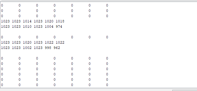
This is the code for the raw value example:
 #include <QTRSensors.h>
#define NUM_SENSORS 6 // number of sensors used
#define NUM_SAMPLES_PER_SENSOR 4 // average 4 analog samples per sensor reading

// sensors 0 through 5 are connected to analog inputs 0 through 5, respectively
QTRSensorsAnalog qtra((unsigned char[]) {0, 1, 2, 3, 4, 5},
NUM_SENSORS, NUM_SAMPLES_PER_SENSOR, QTR_NO_EMITTER_PIN);
unsigned int sensorValues[NUM_SENSORS];

void setup(){  delay(500);
  Serial.begin(9600); // set the data rate in bits per second for serial data transmission
  delay(1000);}
void loop()
{
  qtra.read(sensorValues);
  unsigned char i;
  for (i = 0; i < NUM_SENSORS; i++)
  {
    Serial.print(sensorValues[i]); // I TOOK OUT THE MATH THAT CONVERTED THE NUMBER TO SOMETHING BETWEEN 1-9
    Serial.print('\t');
  }
    Serial.println();

  delay(2500);
}
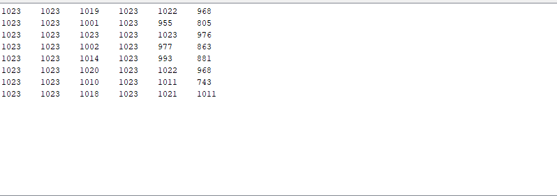
And these are the results:
Thanks for any help in advance.
Summary
This text will be hidden