
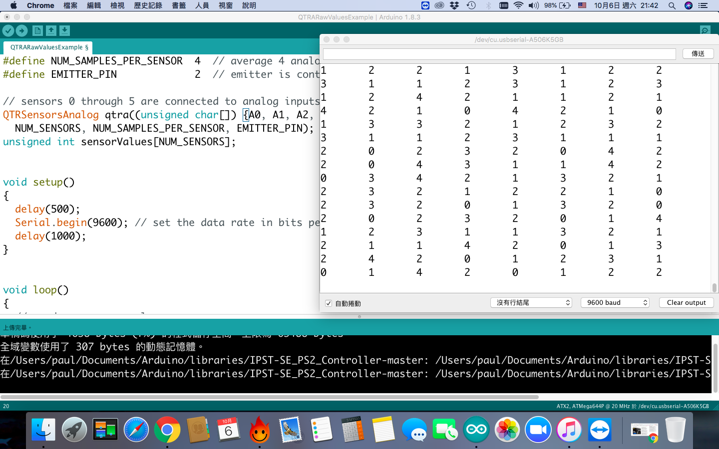
only can read 0~4, please support
Could you post more details about your setup, including pictures of all of your connections? What Arduino are you using, and what are you doing with the sensor during this test?
Brandon
Hi, I am using it to do a line follower. I have bought 3 QTR 8RC & A last week! The other two is working good. I am using ardunio from inex ardunio board.

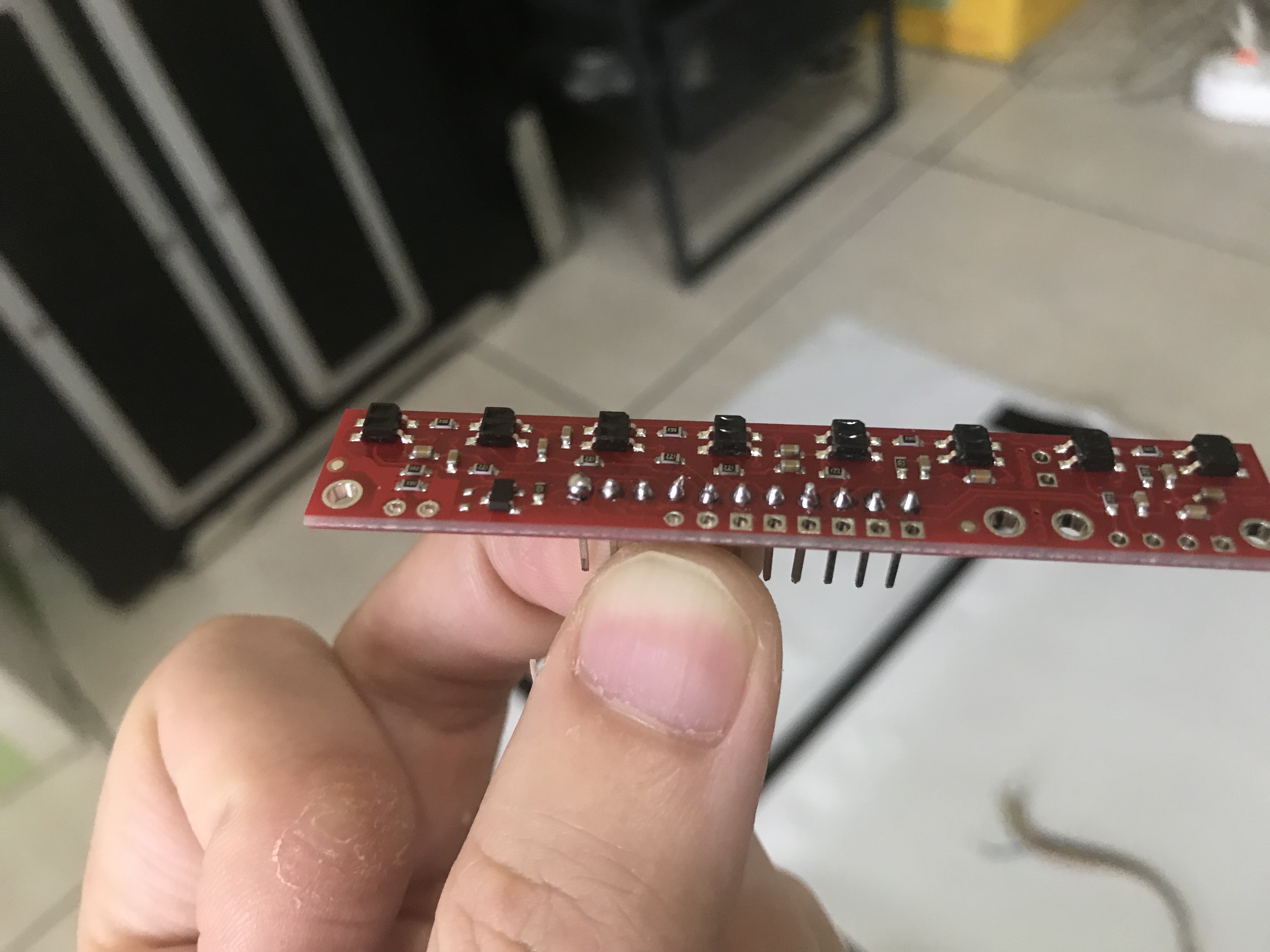
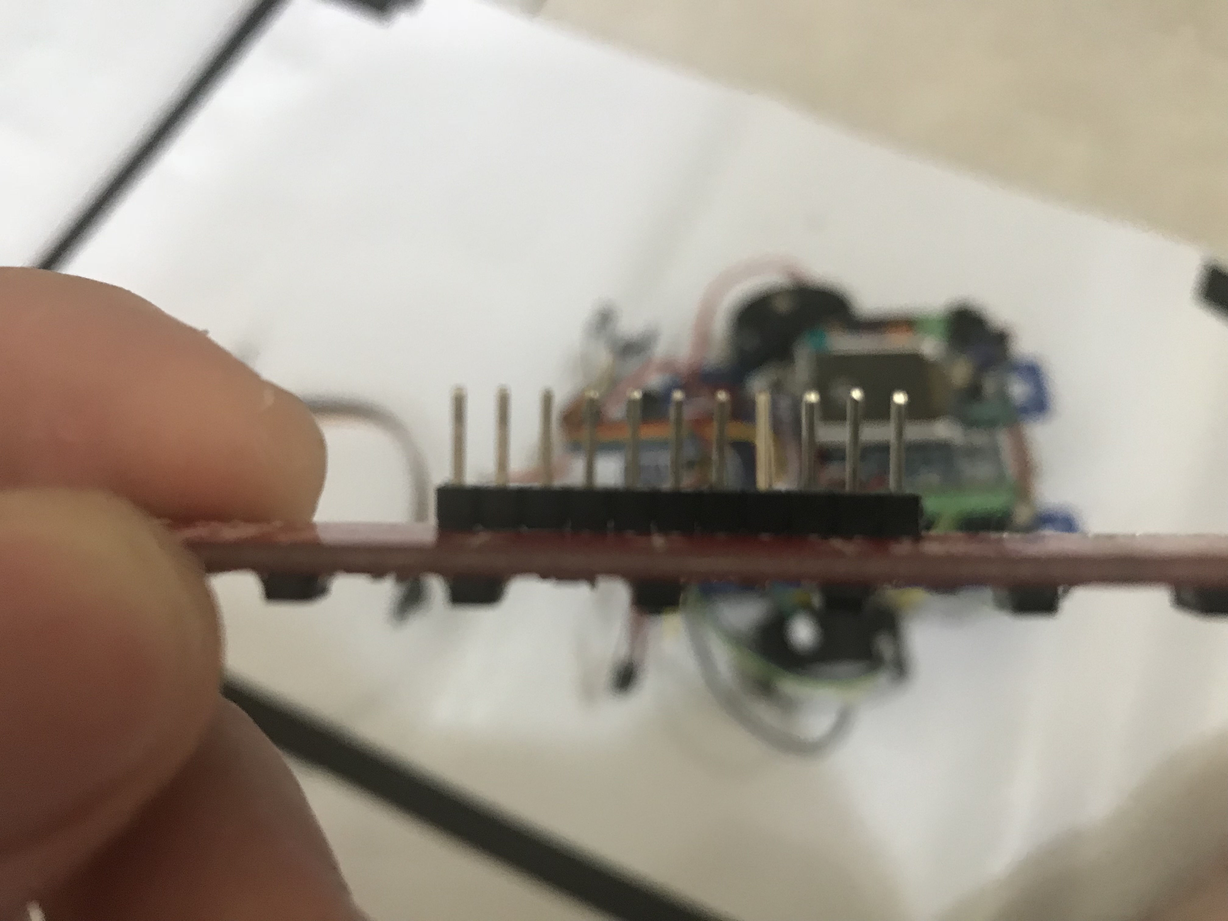
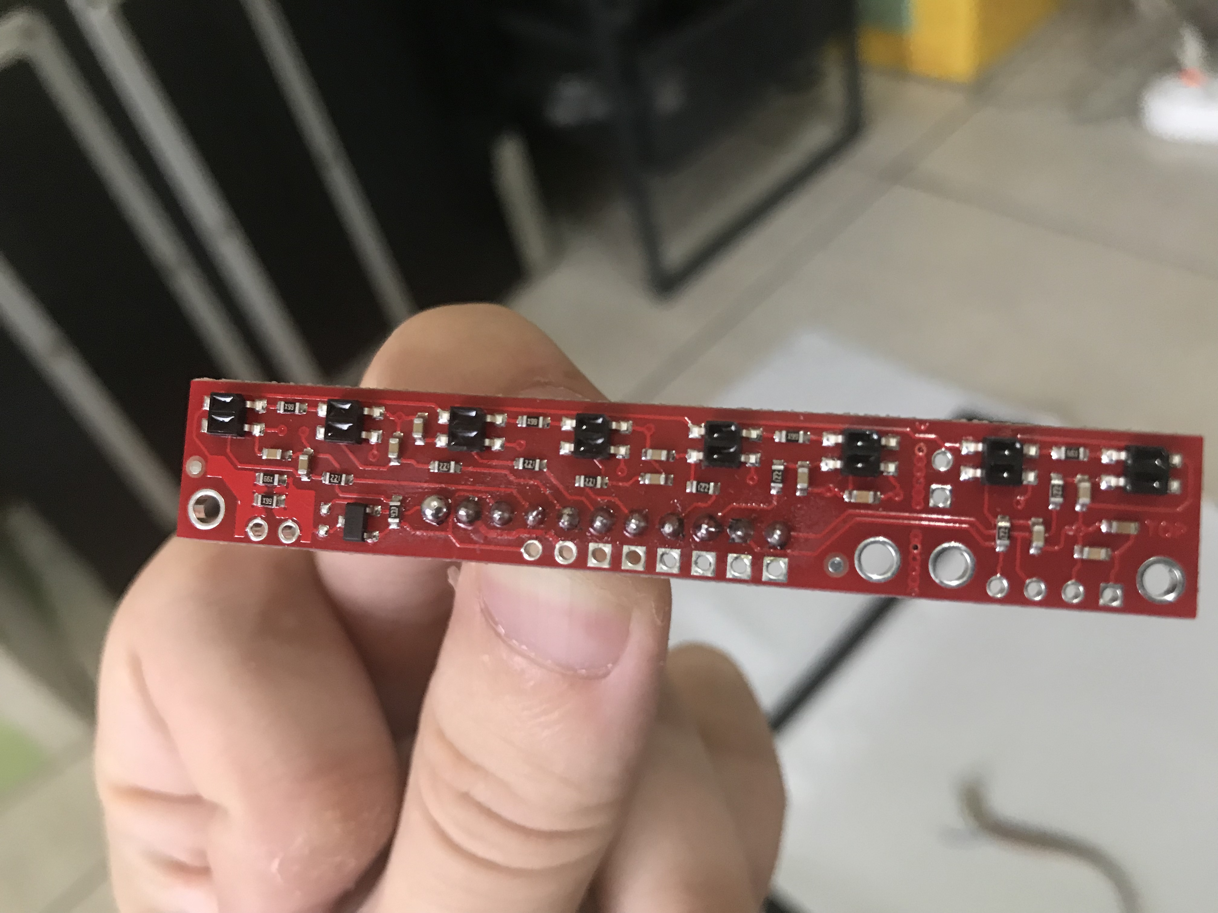
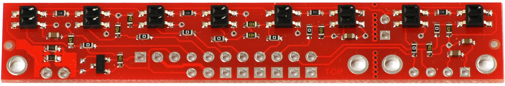
The QTR board shown in your pictures is a QTR-8RC; it looks like you might have confused it for the QTR-8A you have.
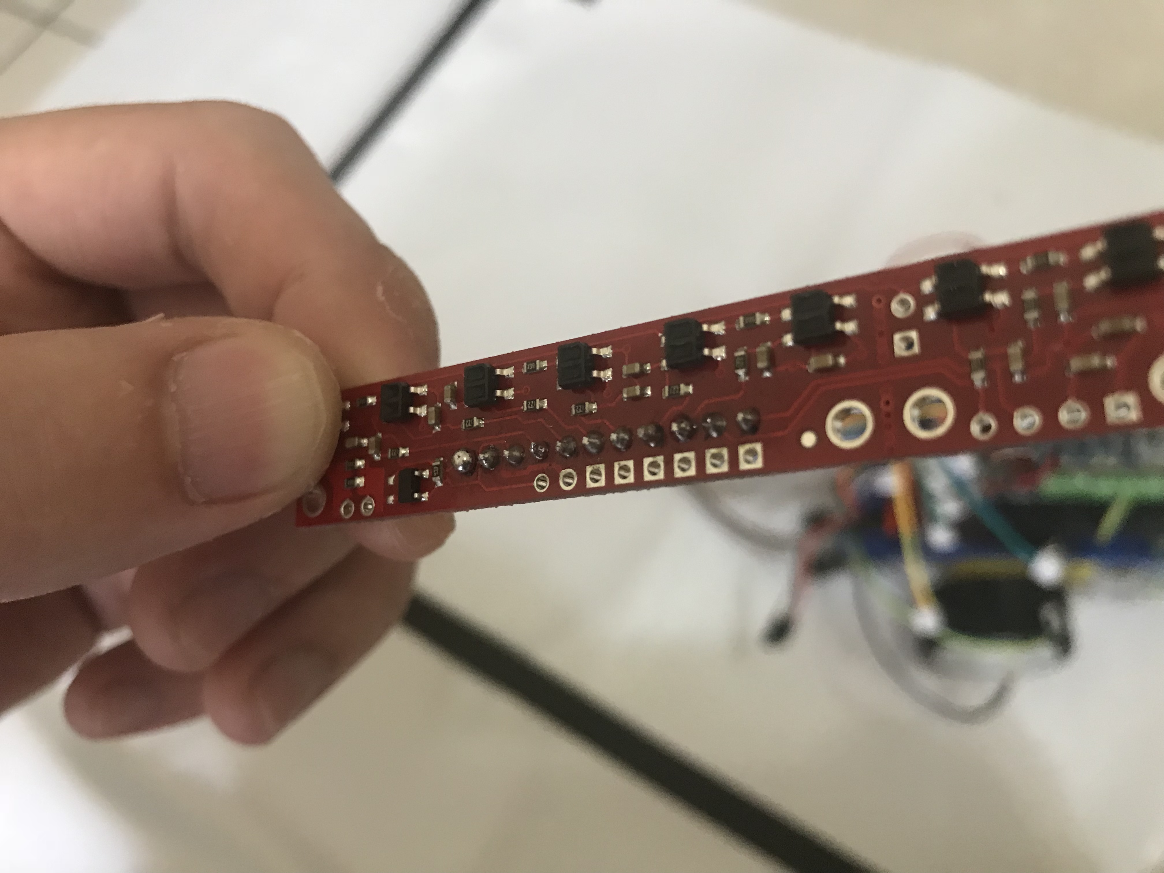
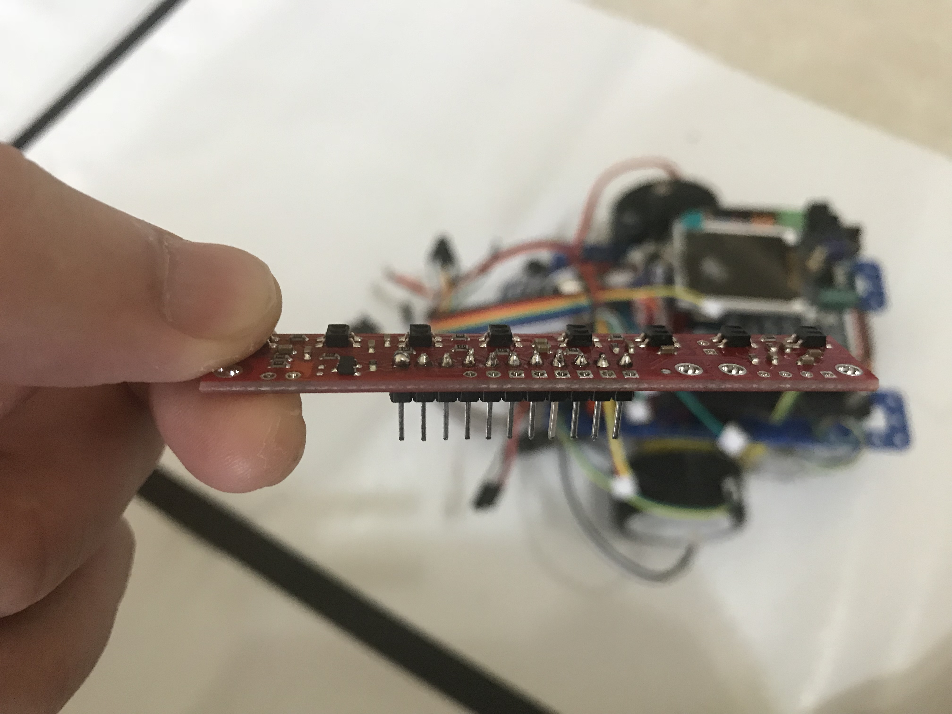
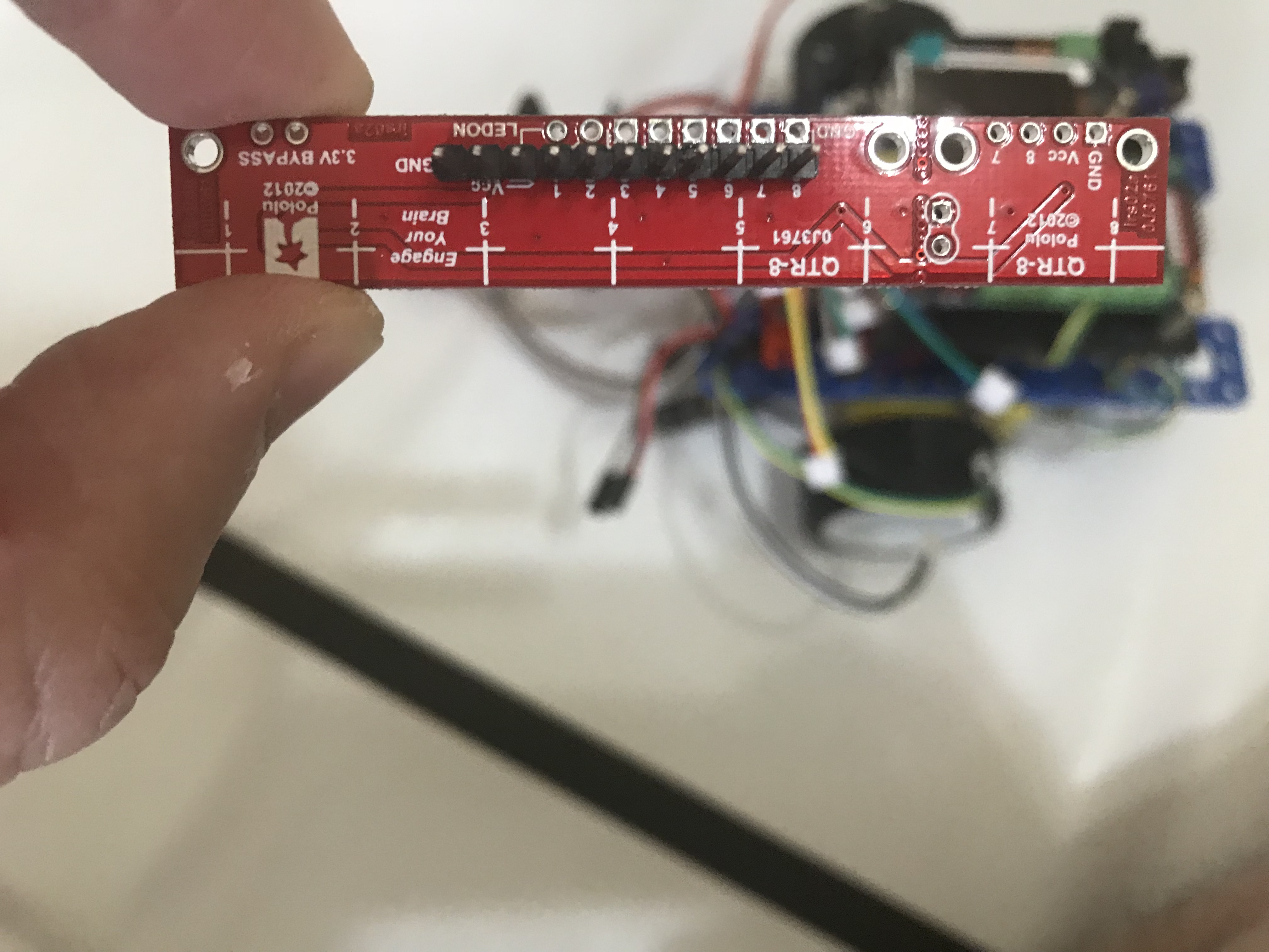
You can tell them apart by looking at the components on the board (several of the resistors on the QTR-8A are swapped out for capacitors on the QTR-8RC). Here are some reference pictures:
QTR-8RC:
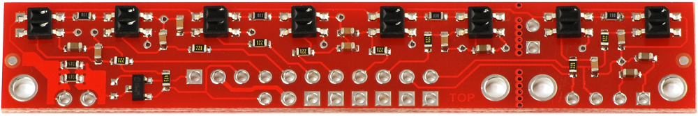
QTR-8A:
Brandon
Hi, I got it now, I was used the wrong model code. For another questions are
- what is important to do the sensor calibrate?
- because my current code is PID line follower and I have own error adjustment definitions
Right to left
00000001 error4
00000011 error3
00000010 error2
00000110 error1
00011000 error0
00110000 error-1
01000000 error-2
11000000 error-3
10000000 error-4
And I have set a middlevalue=500, when sensor value > middlevalue then is on black line. My line is 3 cm wide 2 sensors on black is detected in almost routine. But in some curve routine still will miss line. I recognize some time will meet 3 sensors on black line but I checked possibilities those sensors will not have similar result, 2 is near 800 and 1 is 400.
Can you give me suggestions to improve my line follower sensors read performance. Thanks
Calibrating the sensors can give you more reliable readings. Unless you are just using the raw sensor values (e.g. the read() function), you should do a calibration.
It looks like your method for determining the line position is unnecessarily limiting. For example, if I understand your description correctly, you only have 9 unique values of error. Is there a reason you are not using the readLine() function from the QTR sensor Arduino library? This function will return a value between 0 and 7000 (since you are using 8 sensors), giving you much more resolution. You can find more information about this command in the Arduino Library for the Pololu QTR Reflectance Sensors documentation.
You might also find our line follower example for the Zumo robot helpful; the implementation of the library functions should be the same.
Brandon
Hi
For now I am just using read function. and I changed my error pattern
00000001 7

00000011 6

00000010 5

00000110 4

00000100 3

00001100 2

00001000 1

00011000 0

00010000 -1

00110000 -2

00100000 -3

01100000 -4

01000000 -5

11000000 -6

10000000 -7
it working fine now, I am just wondering is it readline () function and calibrating will have big different with my current method? And because I have sharp turn left and right 90 degrees and 180 degrees in the line routine, I am not clear how to make a definition with readline() and pd control function.
Cuz I am trying to make a fast and stable PD line follower.
As I mentioned in my previous post, the readLine() function has a much larger range of outputs, which will give you several orders of magnitude more resolution in your readings. Also, please note that you can still use the individual sensor readings to detect sharp turns. This is the method that most (if not all) of the line following robots used in our recent competition. You can see the results in the video on the [LVBots May 2018 line following competition][0] blog post. In particular, the robots doing the more advanced course (with sharp turns) can be seen around the 5:00 mark:
The readLine() function needs to be passed an array, which is used to store all of the calibrated readings from each sensor, so you can use the readings stored in that array to detect when multiple sensors are seeing the black line (e.g. when the middle and farthest right sensors are seeing the line, you are probably at a sharp right turn).
If you have any particular questions about using readLine() that you couldn’t work out from referencing the example I linked to, I would be glad to try to answer them.
Brandon
Hi I tried readline function and try to fit it into my code. But I am confused about the pid error value calculation. Before I will set a error definitions with ir sensors pattern. But I saw from the example
  int position = qtrrc.readLine(sensors);
  int error = position - 2000;

  int motorSpeed = KP * error + KD * (error - lastError);
  lastError = error;
What is 2000 is? Or 2500? And 1000? Because in different examples they use different values.
And Calibration functions, I don’t see how it work to help in line follow code. Does it will stored calibration value or just let me know the values it detect?
Actually I used readline function and calibration function my line follower is not run
And below is my testing code
#include <ATX2.h>	// ATX2 Board
#include <QTRSensors.h>
int lastError = 0;
#define NUM_SENSORS             8  // number of sensors used
#define NUM_SAMPLES_PER_SENSOR  4  // average 4 analog samples per sensor reading
#define EMITTER_PIN 18 //QTR_NO_EMITTER_PIN     // emitter is controlled by digital pin 2
QTRSensorsAnalog qtra((unsigned char[]) {A0, A1, A2, A3, A4, A5, A6, A7},
  NUM_SENSORS, NUM_SAMPLES_PER_SENSOR, EMITTER_PIN);
float KP = 13;
float KD = 20;
int M1 = 85;
int M2 = 85;
void setup(){
  OK();
}
void loop()
{
unsigned int sensors[8];
  // get calibrated sensor values returned in the sensors array, along with the line
  // position, which will range from 0 to 2000, with 1000 corresponding to the line over
  // the middle sensor
  int position = qtra.readLine(sensors);

  // compute our "error" from the line position.  We will make it so that the error is zero
  // when the middle sensor is over the line, because this is our goal.  Error will range
  // from -1000 to +1000.  If we have sensor 0 on the left and sensor 2 on the right,
  // a reading of -1000 means that we see the line on the left and a reading of +1000
  // means we see the line on the right.
  int error = position - 1000;

  // set the motor speed based on proportional and derivative PID terms
  // KP is the a floating-point proportional constant (maybe start with a value around 0.1)
  // KD is the floating-point derivative constant (maybe start with a value around 5)
  // note that when doing PID, it's very important you get your signs right, or else the
  // control loop will be unstable
  int motorSpeed = KP * error + KD * (error - lastError);
  lastError = error;

  // M1 and M2 are base motor speeds.  That is to say, they are the speeds the motors
  // should spin at if you are perfectly on the line with no error.  If your motors are
  // well matched, M1 and M2 will be equal.  When you start testing your PID loop, it
  // might help to start with small values for M1 and M2.  You can then increase the speed
  // as you fine-tune your PID constants KP and KD.
  int m1Speed = M1 + motorSpeed;
  int m2Speed = M2 - motorSpeed;

  // it might help to keep the speeds positive (this is optional)
  // note that you might want to add a similiar line to keep the speeds from exceeding
  // any maximum allowed value
  if (m1Speed < 0)
    m1Speed = 0;
  if (m2Speed < 0)
    m2Speed = 0;
  motor(5,m1Speed);
  motor(6,m2Speed);
  // set motor speeds using the two motor speed variables above
}
The readLine() function returns a value between 0 and 1000 × N, where N is the number of sensors you are using minus 1. For example, if you are using 8 sensors, readLine() will return a number between 0 (when the line is under the first sensor) and 7000 (when the line is under the last sensor). Since you want the error to be 0 when the line is in the middle, you can set your error to readLine()-3500. This will result in an error value between -3500 and +3500, with 0 in the center.
It does not look like you have any calibration in the code you posted. As I mentioned before, unless you are just using the raw readings from the sensors, you should do a calibration. This calibration is required to scale the readings to better, more reliable values for your application. The readLine() function uses these calibrated readings and if you try to use it without calibrating the calibrated readings will just be 0 at all times. Also, please note that when you are calibrating, the sensors need to be exposed to the extremes you expect them to see during use, so you should make sure they all get passed over the black line and the white space on your course during calibration. In the examples I linked you to, the robot turns in place during calibration in order to move the sensors over the line so you do not need to manually move it.
Brandon
So is it qtr rc and 8A is all set position -3500? And if I use readline function I don’t need to do the calibration? Or I need to calibration in the setup() section?
The readLine() function works the same way for either version of the sensor (e.g. if you are using 8 sensors, the output is from 0 to 7000). You need to calibrate the sensors in order to use the readLine() function. You only need to do a calibration routine once before using the readLine() function, so doing it in setup() before entering your main loop should be fine.
Brandon
Hi I got problem with the pd line follower I think my pd is good for follow line but dont know why with 90 degree turn left the robot will side out? Is it the sensor hardware is not read correctly? below is my video
https://drive.google.com/file/d/189RluDcK4Q2MR3bLyrjx7PUHygJM1eod/view?usp=sharing
Hello.
I fixed your Google drive video link to just show a plain link.
Your line-following robot seems to be handling the turns well, except the last sharp turn. It looks like your robot is increasing its speed just before it enters the last turn and reacting too strongly. You might be able to reduce the overshoot by turning your PD constants more, but you probably will need to add a special case in your loop to slow down your robot even more when detecting 90 degree turns.
- Amanda
Is it use readline() as well? Any example to slow down at the 90 degree turn?
What are you referring to?
We do not have any specific code examples. However, you might find it helpful to look at the MazeSolver code for the Zumo Shield to get an idea of how to detects left and right (90 degree) turns. You can find the example code in the “examples” folder on the Zumo Shield Arduino library’s GitHub page.
- Amanda
Hi I am wondering about qtr8a, if all white is it will get back position 0 and all black should get back 7000? But for now when my all sensors on black just return 3500 is it correct?
It sounds like you are referring to the readLine() return values. As @BrandonM mentioned in his earlier post:
The readLine() function returns an estimated position of the line with respect to the sensors. The function is not useful for determining if all sensors are seeing black (or white). You would need to check each sensor value individually to determine if all sensors are over a dark or light spot.
- Amanda
Hello, do I need to turn the led on during the calibration? Is it must be pin 2 or I can indicate by my self?