
Hi, I managed to make this sensor work. However, I cant visualise the current flow in the circuit, maybe someone can help me?
The manual says to charge up the capacitor, then followed by discharging, and the rate of discharge will be determined by the reflectivity of surface.
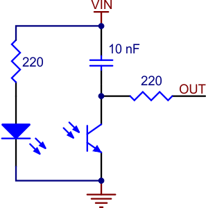
If you apply a voltage at OUT, how would that charge up the capacitor? Since OUT=Vin wouldnt voltage across capacitor be 0V?
From how I see it, the capacitor should discharge instead because voltage is 0 and it shouldnt hold any charge, followed by being charged up and the rate of charging will vary, kind of counter logic.
Seems like a elementary issue but I cant really see it O.o