Have something strange happening using the QTR library with a single QTR1C sensor. I modified the example code for raw values like:
#define NUM_SENSORS   1     // number of sensors used
#define TIMEOUT       2500  // waits for 2500 microseconds for sensor outputs to go low
#define EMITTER_PIN   QTR_NO_EMITTER_PIN     // emitter is controlled by digital pin 2

// sensors 0 through 7 are connected to digital pins 3 through 10, respectively
QTRSensorsRC qtrrc((unsigned char[]) {5},
  NUM_SENSORS, TIMEOUT, EMITTER_PIN);
unsigned int sensorValues[NUM_SENSORS];


void setup()
{
  delay(500);
  Serial.begin(9600); // set the data rate in bits per second for serial data transmission
  delay(1000);
}


void loop()
{
  // read raw sensor values
  qtrrc.read(sensorValues);

  // print the sensor values as numbers from 0 to 2500, where 0 means maximum reflectance and
  // 2500 means minimum reflectance
  for (unsigned char i = 0; i < NUM_SENSORS; i++)
  {
    Serial.print(sensorValues[i]);
    Serial.print('\t'); // tab to format the raw data into columns in the Serial monitor
  }
  Serial.println();

  delay(250);
}
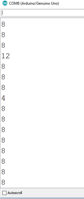
The values printed are either 4 or 8, mostly 8’s. I did a search of the forum and came across this post that implements reading the sensor without the library, https://forum.pololu.com/t/code-snippet-for-qtr-1rc/3548 and gave it a try with the same hardware setup and it appears to be working, depending on the reflectance the values are changing. Here is the code that seemed to work based on the reference link.
unsigned long startTime;
unsigned long elapsedTime;

void setup() {
  Serial.begin(9600);

}

void loop() {
{
//************* Read One Sensor and Display Value on LCD
  pinMode(5, OUTPUT);       // Set sensor pin to output
  digitalWrite(5, HIGH);
  delayMicroseconds(50);          // Charge capacitor for 50 usec
  pinMode(5,INPUT);
  digitalWrite(5, LOW);
  startTime = micros();
  while(digitalRead(5) == HIGH)
  {
  }
  elapsedTime = micros() - startTime;
  Serial.println(elapsedTime);
}
}
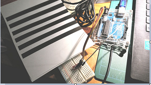
I looked over your code and did not see anything wrong with it. Have you tried running the example code as is? If not, can you load the unmodified sketch onto your Arduino board, move the sensor across your line, and post a screenshot of the Serial Monitor here? Did you execute the same test with both codes? Can you post pictures of your setup and test surface? Also, which Arduino board are you using?
Think I got the issue resolved with the example. In looking a little more closely at the code snippet that I used and the example I noticed the timeouts were different. In the example it is set at 2500 micros and the snippet was at 5000 micros. I changed the timeout to 5000 and the example started working no problem. Going to play a little more with the examples and if I run into any other issue I will let you know.
Thanks for listening.
Mike
UPDATE: Think I spoke to soon. Went to run the calibrate sketch and that failed even with increasing the timeout. I went back and reran the rawvalues sketch from the library and it started doing the same thing with all 8’s and 4’s. Not sure whats going on.
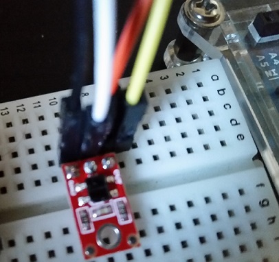
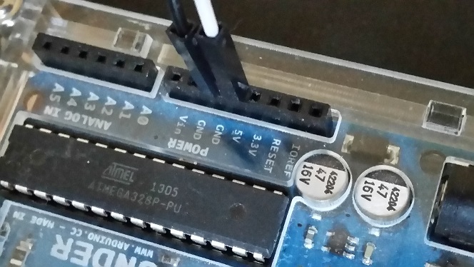
It sounds like there might be something wrong with your connection to the QTR sensor array. Can you post close-up pictures showing your connections between the Arduino Uno and QTR board? Also, can you try running the other code and post its output here?
Thanks for posting better pictures of your setup. Your soldering and connections look fine from what I can see. Can you verify that the wire connected to the OUT pin on the QTR sensor is connected to pin 5 on your Arduino board?
How are you testing the QTR sensor? Are you sliding the test surface (or paper) over the sensor? It would be best if you can post a video showing your test procedure.