Hi,
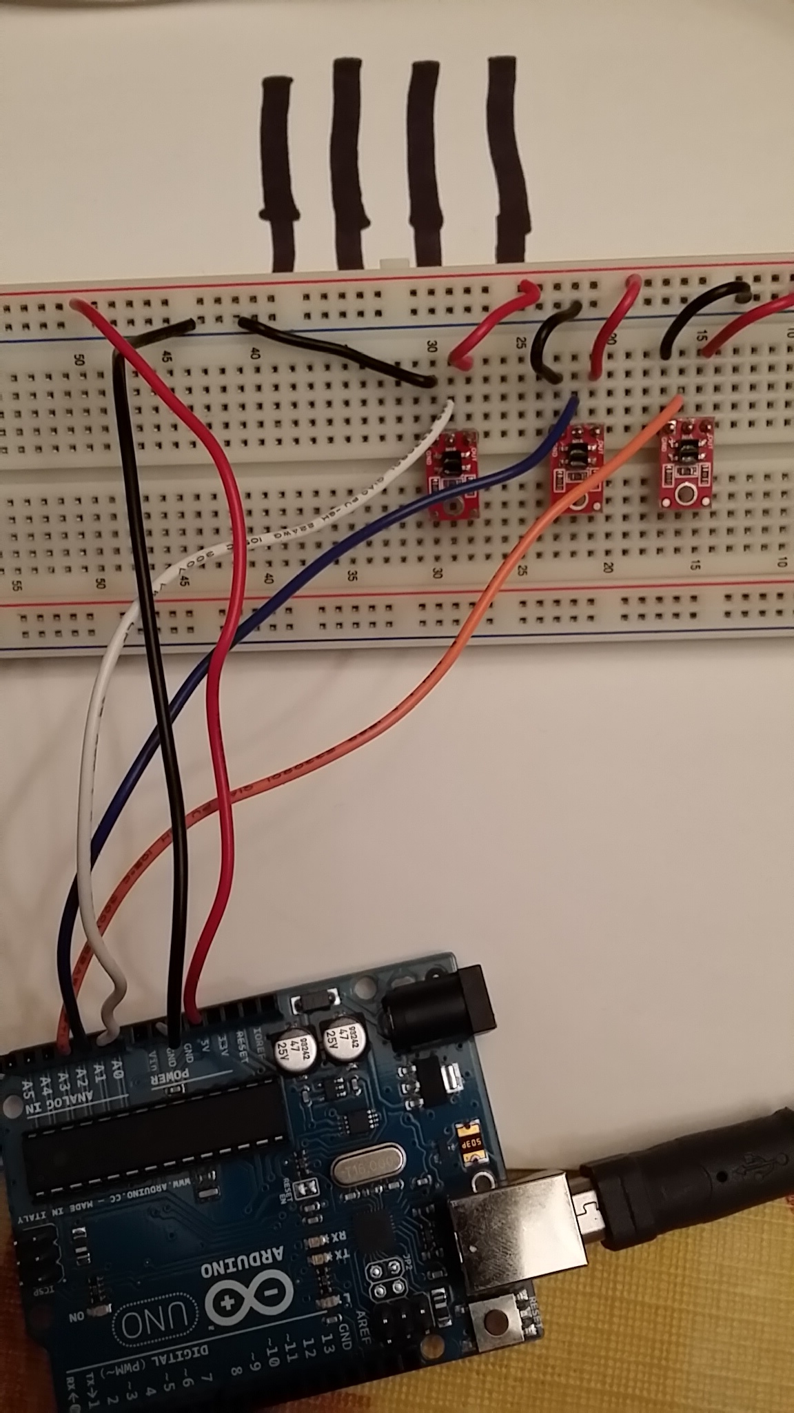
I would like to know if my 3 sensors are broken. I’m using the QTRA example code and have my 3 sensors on a breadboard. I’ve tried various ways to get a min reading of zero but it stays high for everything. In my picture I flip the breadboard over and jiggle the sensors over the lines during calibration. I cannot get ‘calibration min.’ on any of the three sensors to zero (see output list).
Pic, code and output attached. I appreciate your help.
#include <QTRSensors.h>

// This example is designed for use with six QTR-1A sensors or the first six sensors of a
// QTR-8A module.  These reflectance sensors should be connected to analog inputs 0 to 5.
// The QTR-8A's emitter control pin (LEDON) can optionally be connected to digital pin 2,
// or you can leave it disconnected and change the EMITTER_PIN #define below from 2 to
// QTR_NO_EMITTER_PIN.

// The setup phase of this example calibrates the sensor for ten seconds and turns on
// the LED built in to the Arduino on pin 13 while calibration is going on.
// During this phase, you should expose each reflectance sensor to the lightest and
// darkest readings they will encounter.
// For example, if you are making a line follower, you should slide the sensors across the
// line during the calibration phase so that each sensor can get a reading of how dark the
// line is and how light the ground is.  Improper calibration will result in poor readings.
// If you want to skip the calibration phase, you can get the raw sensor readings
// (analog voltage readings from 0 to 1023) by calling qtra.read(sensorValues) instead of
// qtra.readLine(sensorValues).

// The main loop of the example reads the calibrated sensor values and uses them to
// estimate the position of a line.  You can test this by taping a piece of 3/4" black
// electrical tape to a piece of white paper and sliding the sensor across it.  It
// prints the sensor values to the serial monitor as numbers from 0 (maximum reflectance)
// to 1000 (minimum reflectance) followed by the estimated location of the line as a number
// from 0 to 5000.  1000 means the line is directly under sensor 1, 2000 means directly
// under sensor 2, etc.  0 means the line is directly under sensor 0 or was last seen by
// sensor 0 before being lost.  5000 means the line is directly under sensor 5 or was
// last seen by sensor 5 before being lost.


#define NUM_SENSORS             3  // number of sensors used
#define NUM_SAMPLES_PER_SENSOR  4  // average 4 analog samples per sensor reading
#define EMITTER_PIN             QTR_NO_EMITTER_PIN  // emitter is controlled by digital pin 2

// sensors 0 through 5 are connected to analog inputs 0 through 5, respectively
QTRSensorsAnalog qtra((unsigned char[]) {0, 1, 2, 3, 4, 5},
  NUM_SENSORS, NUM_SAMPLES_PER_SENSOR, EMITTER_PIN);
unsigned int sensorValues[NUM_SENSORS];


void setup()
{
  delay(500);
  pinMode(13, OUTPUT);
  digitalWrite(13, HIGH);    // turn on Arduino's LED to indicate we are in calibration mode
  // print the calibration minimum values measured when emitters were on
  Serial.begin(9600);
  Serial.println("Starting calibration in 5 seconds");
  delay(1000); // wait for window to be opened
  Serial.println(", 4");
  delay(1000); // wait for window to be opened
  Serial.println(", 3");
  delay(1000); // wait for window to be opened
  Serial.println(", 2");
  delay(1000); // wait for window to be opened
  Serial.println(", 1");
  delay(1000); // wait for window to be opened
  Serial.println(", 0");
  for (int i = 0; i < 400; i++)  // make the calibration take about 10 seconds
  {
    qtra.calibrate();       // reads all sensors 10 times at 2.5 ms per six sensors (i.e. ~25 ms per call)
  }
  digitalWrite(13, LOW);     // turn off Arduino's LED to indicate we are through with calibration
  //Print calibrations
  for (int i = 0; i < NUM_SENSORS; i++)
  {
    Serial.print("Calibrated min. ");
    Serial.print(i);
    Serial.print(" = ");
    Serial.print(qtra.calibratedMinimumOn[i]);
    Serial.print(' ');
  }
  Serial.println();

  // print the calibration maximum values measured when emitters were on
  for (int i = 0; i < NUM_SENSORS; i++)
  {
    Serial.print("Calibrated max. ");
    Serial.print(i);
    Serial.print(" = ");
    Serial.print(qtra.calibratedMaximumOn[i]);
    Serial.print(' ');
  }
  Serial.println();
  Serial.println();
  delay(1000);
}


void loop()
{
  // read calibrated sensor values and obtain a measure of the line position from 0 to 5000
  // To get raw sensor values, call:
  //  qtra.read(sensorValues); instead of unsigned int position = qtra.readLine(sensorValues);
  unsigned int position = qtra.readLine(sensorValues);

  // print the sensor values as numbers from 0 to 1000, where 0 means maximum reflectance and
  // 1000 means minimum reflectance, followed by the line position
  for (unsigned char i = 0; i < NUM_SENSORS; i++)
  {
    Serial.print("Sensor ");
    Serial.print(i);
    Serial.print(" = ");
    Serial.print(sensorValues[i]);
    Serial.print('\t');
  }
  Serial.println(); // uncomment this line if you are using raw values
  //Serial.println(position); // comment this line out if you are using raw values

  delay(500);
}
Starting calibration in 5 seconds
, 4
, 3
, 2
, 1
, 0
Calibrated min. 0 = 195 Calibrated min. 1 = 195 Calibrated min. 2 = 195
Calibrated max. 0 = 196 Calibrated max. 1 = 196 Calibrated max. 2 = 196

Sensor 0 = 0	Sensor 1 = 0	Sensor 2 = 0
Sensor 0 = 0	Sensor 1 = 0	Sensor 2 = 0
Sensor 0 = 1000	Sensor 1 = 1000	Sensor 2 = 0