I have a 555 timing circuit that uses a switch to start the timing cycle. Makes no difference if the switch is held closed or not, as the timing cycle will not restart until the switch is released and re-activated.
I would like to replace that switch utilizing the output of the QTR-1A and not quite sure how to interface it. I was thinking of using a N-Channel FET to replace the switch, but the output of the QTR sensor when an object is sensed goes low. Or maybe a solid-state relay. The input of a solid-state relay is an LED so maybe that could be driven by the output of the QTR, but then again the output of the QTR is normally high (supply voltage) which means the solid-state relay would be engaged when no object is sensed. Could I just hook up the LED (relay) so that the normal QTR high output is blocked by the LED since it is a diode and then it will light up (engage relay) when the QTR output goes low when a object is sensed?
There is probably a much simpler solution than your solid state relay idea, but in general you can’t just replace a physical switch with some solid state electronics - you need to actually understand the circuit to substitute the right parts. For example, if the switch is being used to drive a line low, you could just use the QTR-1A directly as an input to that line. If you need to drive a line high, a simple transistor inverter might be all you need.
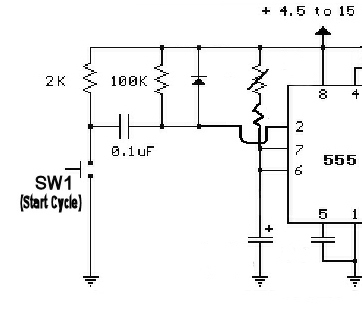
Ok, as you can see in the below schematic, the switch is actually taking Pin 2 (trigger) of the 555 to ground when the switch is closed. Are you saying to connect the out of the QTR to where the switch is and that when an object is sensed and the output of the QTR goes low, that it in effect takes the pin 2 of the 555 low, as would the switch? Would’nt the normal high voltage of the QTR mess with the 555 circuit? Where that switch is there should not normally be a high voltage.
Since the supply voltage of the 555 circuit (5 volt) is going through a 2k resistor before the switch, maybe I could go from the QTR output to a 2k resistor and from there connect to where the switch is? Am I missing something here?
Could’nt I just use a PNP transistor? It switches on when the base goes low (hence, when the QTR output goes low, it would switch on the transistor. If the emitter and collector is connected where the switch is now, it should provide the same functionality as the switch, no?
Okay, that makes it a bit more clear. Do you understand how this circuit works?
I have not thought it through enough, but it looks like it might work if you remove the 2k resistor and connect the output of the QTR-1A directly to that capacitor.
The 2K resistor must remain in the circuit, it is used to allow the capacitor to discharge, otherwise the cap would only work once.
I’m going to try a PNP transistor or a small solid-state relay. Using a regular coil relay would require protection against back EMF feeding into the QTR-1A when the magnetic field collapses and you would also have the annoying clicking sound of the mechanical relay. I would probably feel safer using a solid-state relay with an inverter transistor which would turn on the relay when QTR output goes low(when a object is sensed).
Although it should work with just a PNP transistor using a resistor between it and the QTR output to limit current to the transistor.
You are right about the function of that 2k resistor, but the 47k resistor in the QTR-1A can probably play the same role. I think you do not really know how to use a transistor - with what you described, the voltage on the emitter of that transistor will be guaranteed to be quite a lot higher than the output of the QTR-1A. I really recommend reading over some basic transistor tutorials before you try it!