We’re looking to switch cameras to more of an OEM type rather than a name brand. However, for the camera we’re interested in it has a control board with RS-485 interfacing. Is it possible to communicate with an RS-485 receiver with the Maestro? If so, does anyone know how I could do that?
I should also add that the camera we’re looking at has VISCA and PELCO P/D protocols which I assume are transmitted over the RS485 signal. I’m not completely sure as this is new territory for me.
I am not familiar with the VISCA or PELCO P/D protocols, and it is not entirely clear to me how you want to use the Maestro and your camera together, but the Maestro’s TTL serial interface does not accept RS-485 directly, so you would need some kind of adapter to convert the signals. Additionally, please note that if you are using a script, and want it to send TTL serial signals, you would need to use one of the Mini Maestro controllers since the SERIAL_SEND_BYTE command is not available on the Micro Maestro.
Ultimately, I suspect a more general purpose microcontroller, such as an Arduino or one of our Arduino-compatible A-Star controllers is probably a better option, although you would still need an adapter.
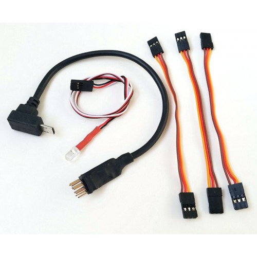
Thanks for the reply! Let me be a little more detailed about what we’re doing and let’s see if this changes your answer or not. We’re currently sending outputs to the USB on the Maestro from a Raspberry Pi which then tells different channels on the Maestro to output specific PWM signals. These signals currently are getting translated by a chip/cord that communicates with a Sony camera. Here is the chip/cord we are currently using:
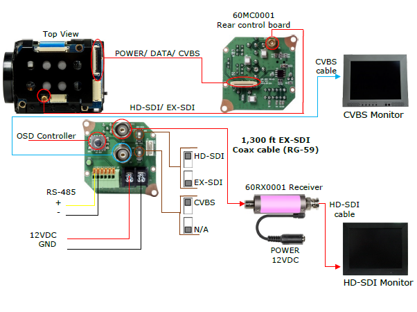
We are hoping to bypass this cord (if possible) and connect directly into an OEM block camera which delivers the control functions very basically via RS-485 signals. Here is the camera and control board we are looking at:
So in this case the control board connected to the camera would only receive the PWM signals coming from the Maestro in order to move the zoom. I was thinking it may be possible to have the control board programmed to understand the PWM signals at the RS-485 receiver? Or maybe have some sort of converter similar to our chip/cord above which then connects to the RS-485 port. Or are you saying this is absolutely impossible and we must use the TTL serial interface on the Maestro to communicate at all? (Currently we have no need for the TTL serial interface. We just use the basic 3 pin channels with our chip/cord and I have no knowledge yet of how to use the TTL serial interface to accomplish our needs).
I am not familiar with that camera control board, but I suspect it is unlikely that it is able to be reprogrammed to accept RC signals instead of RS-485. You might try contacting the manufacturer just in case.
Since you have a Raspberry Pi in the system already, you might consider just using that to send serial signals to the camera controller through an RS-485 adapter like this one (instead of adding complexity with other controllers). We do not have any specific examples for using a Raspberry Pi with an RS-485 device like that, but there are a lot of Raspberry Pi resources available online that could be helpful. A quick search for “how to connect Raspberry Pi and RS-485” turned up this tutorial, which seems close to what you would want.
However, please note that it looks like that adapter outputs 5V for the signal back to the Raspberry Pi. That tutorial doesn’t account for the voltage difference, which could damage the Raspberry Pi. To avoid damaging the electronics, you should either use a simple voltage divider or a logic level shifter to reduce the 5V signal down to 3.3V. Alternatively, if you do not need to receive data back from the camera controller, you could leave the connection from the adapter’s TX pin to the Raspberry Pi’s RX pin disconnected.
Yes, I think you’re totally right. Either we need another controller (such as an Arduino microcontroller you recommended in your first reply) to translate the PWM signals to RS-485 (which I believe is essentially what the chip in our custom RC cord is doing, but specific to the Sony camera’s multi-terminal input), or like you said remove all the complexity of going from the Pi > to the Maestro > to a controller > to the camera control board and instead simply go from Pi > to an RS-485 adapter > to the camera control board, and then configure the correct signals on the Pi for communication with the camera control board via the RS-485 serial communication (which uses the VISCA Sony trademarked protocol for which we can get documentation on).
If you have a moment, let me know if it sounds like I’m understanding correctly. I think I’m on the right path and understand my options now. Really appreciate your help!