I would like to make a CAD part for you pushbutton power switch so I can attach it to my pcb, but the holes where the push button go aren’t on the same .1" grid.
Do you have a CAD file with these dimension, or just give me their offsets in relation to one of the other holes? I really only need the one towards the middle of the board since the other button hole just looks to be ground.
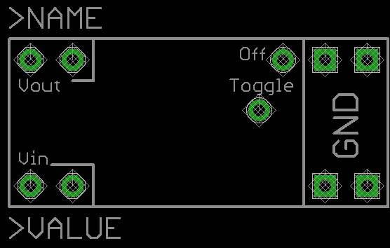
The two pins for the pushbutton are 6.5mm apart from each other and are 0.125" away from the row of pins on the VOUT side of the board. The pushbutton pin closest to the edge of the board is in line with the ground pins in the corners. If you email us at support@pololu.com, I can provide a DXF file that includes the board’s dimensions and drill locations.
Attached is a Eagle Cad script which will generate the Pololu Pushbutton switch. Hasn’t been tested, but I just ordered some boards that use it so I’ll know in a week or so.
Deleted file. See next post.
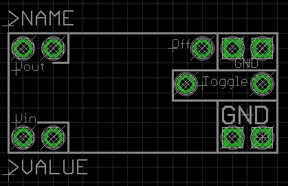
So I just got my first boards in using this part and there’s a mistake. I wrongly assumed that the switch pin near the grounds was also a ground when it isn’t. Fortunately I figured out a work around. Attached is a script with the fixed part. I also made the holes slightly bigger so standard pin strips would fit better. Pololu_power_switch.zip (11.5 KB)