
Having solved the problem of controlling the turning angle for my Pololu RP5 based autonomous robot through the use of a MEMS gyroscope, see “Deriving Angle Of Rotation From A MEMS Gyroscope”
https://forum.pololu.com/t/deriving-angle-of-rotation-from-a-mems-gyroscope/2664/1, I returned to the problem of obstacle avoidance. The tools I now had available gave me the ability to detect the distance to a nearby object through the use of Maxbotix ultrasonic range finders, the LV-EZ0 is being used, and the ability to precisely control the turning angle of the robotic chassis to avoid such an object when detected within a predetermined distance of the moving robot.
Based on past experiments I decided to add two additional Maxbotix ultrasonic range finders to the robot chassis, one at the midpoint on each side of the chassis facing outward at a 90 degree angle to the original forward facing one. This arrangement has the forward facing sensor located on the major axis of the chassis, i.e. the line running the length of the chassis on the midpoint of its width, and the two side facing sensors located on the minor axis of the chassis. Thus placed, each of the sensors lays on a vertex on an isosceles triangle. In particular, for the two side facing sensors a line drawn from the forward facing sensor to a side facing sensor is the hypotenuse of a right triangle whose two legs are formed by the minor axis the sensors are on and the section of the major axis between the front facing sensor and its intersection with the minor axis. All of this is mentioned because when the sensors are placed in this way a 90 degree rotation of the robot chassis will place one of the two side sensors, which one depends on the direction of the rotation, in almost the same position as the forward facing sensor before the rotation was started.
For this attempt at letting the robot move about freely I decided to keep things relatively simple by addressing only objects which are placed in the path of the robot perpendicular to the direction of movement of the robot. If one visualizes a classic rat maze, they will understand the type of object avoidance I am implementing here: only right and left 90 degree turns to avoid and go around an object. Additionally the robot’s priority is to always return to its original direction of travel, e.g. if it turns 90 degrees to the left to avoid an object placed in its path, it will turn 90 degrees to the right as soon as it has gotten past the object.
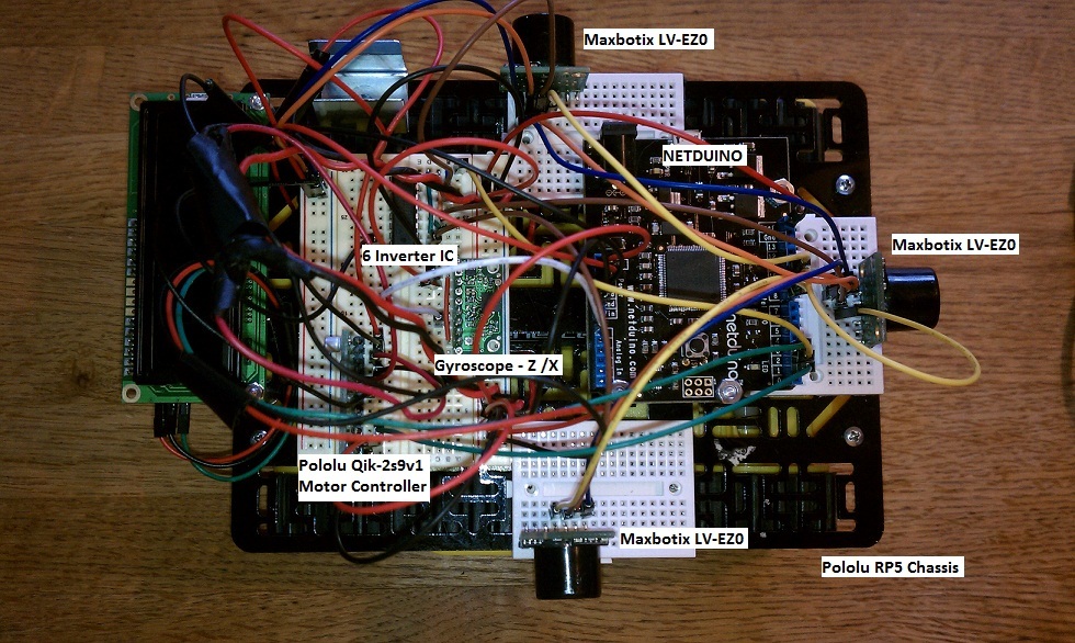
In addition to the sensors the RP5 chassis also carries a Pololu LPY510AL Yaw and Pitch MEMS gyroscope, currently only the Yaw axis is used to control the angle of rotation, a Pololu Qik-2s9v1 dual serial motor controller, a Netduino microcontroller and a TI CD4049UB integrated circuit which is used to invert the serial output of the Maxbotix sensors.
When the robot starts moving in a forward direction distance readings are taken from each of the three sensors in sequence. Each reading is taken by driving the RX pin of a sensor high for 1ms, then driving it low, waiting 49ms and then getting the distance reported by the sensor. The C# code for all of this is below. It should be noted that “s” is defined as “var s = serialInput,” where “serialInput” is a serial I/O class used for serial I/O. Also, the “Thread.Sleep” times correspond to values given in the Maxbotic spec sheets for the sensing cycle of the sensors.
        static OutputPort crtlMaxbotixLeft = new OutputPort(Pins.GPIO_PIN_D10, false);
        static OutputPort crtlMaxbotixCenter = new OutputPort(Pins.GPIO_PIN_D9, false);
        static OutputPort crtlMaxbotixRight = new OutputPort(Pins.GPIO_PIN_D8, false);

                    crtlMaxbotixCenter.Write(true);
                    Thread.Sleep(1);
                    crtlMaxbotixCenter.Write(false);
                    Thread.Sleep(49);
                    center = s.ReadLine();

                    crtlMaxbotixRight.Write(true);
                    Thread.Sleep(1);
                    crtlMaxbotixRight.Write(false);
                    Thread.Sleep(49);
                    right = s.ReadLine();

                    crtlMaxbotixLeft.Write(true);
                    Thread.Sleep(1);
                    crtlMaxbotixLeft.Write(false);
                    Thread.Sleep(49);
                    left = s.ReadLine();
A “state” variable which represents the current status of the motion of the robot is maintained in the logic. This variable can contain one of three values: 0, meaning that the robot is currently moving forward, i.e. it is moving in its desired direction, 1, meaning that the robot has just made a 90 degree left turn, and 2, meaning that the robot has just made a 90 degree right turn.
The “movement” logic is a continuous loop, all logic is contained in a “while (true)” loop. The loop starts with the distance readings from the three sensors being taken as described above. After the distance readings are taken the state variable is checked to determine the action to be taken. There are three possible actions:
State variable = 0. If the robot is moving forward, it will continue to do so as long as the distance reported by the forward facing sensor is greater than 6 inches, 6 inches is the minimum distance reported by the Maxbotix sensor with anything less than 6 inches being reported as 6 inches. If the reported distance is no longer greater than 6 inches, a check will be made of the distances reported by the right and left sensors. If both sensors report a distance of greater than 20 inches, this is an arbitrarily chosen distance which will probably get refined, then the robot will “default” to a 90 degree left turn. If both sensors report a distance of less than 20 inches, the robot will turn 90 degrees in the direction of the greater reported distance. Once such a turn is made, the state variable is set to reflect the turn: 1 or 2.
State variable = 1. Since the robot has just made a 90 degree left turn it will continuously check the distance on the right to determine when it can make a 90 degree right turn to return to its original direction of travel. Once it has determined it can do so it will execute a 90 degree right turn and set the state variable to 0.
State variable = 2: Same as for state variable = 1 but the distance on the left is checked and a 90 degree left turn is made a soon as possible and the state variable reset to 0.
Since the movement logic is a continuous loop a means to stop the robot had to be implemented. This was accomplished by having the logic issue a stop motor command if the distance detected by the front sensor is not greater than 6 inches and the distance reported by each side sensor is less than 10 inches. By having the robot move straight into a small box these conditions are met and the robot stops moving.
Below is a video with a simple demonstration of the above. It should be noted that the grid formed by the floor tiles serve as a nice frame of reference to demonstrate the accuracy of the gyro controlled 90 degree turns.
http://www.youtube.com/watch?v=rAtGVanVlGo