
Please any one help me my qtr-8rc sensor not working not even i apply vcc and ground through arduino mega does it glow led when we plug in please help
Hello,
The LEDs should be on when the board is powered, but they are IR LEDs, so you cannot see them with the naked eye. How are you testing to see if the IR LEDs are on? You can see how you might be able to test those using some cameras in the “Additional Considerations” section of the “QTR-8A and QTR-8RC Reflectance Sensor Array User’s Guide”. Can you post the code you are using on your Arduino Mega? Also, can you post some pictures showing how you have everything connected?
-Derrill
Hi
I am new to qtr sensor i tried QTRRCExample but it does not help me
These are the connections as in arduino qtr library
hi
what should i do with digital pin 20 kindly help me
#include <QTRSensors.h>
#define KP 0.5
#define KD 0
#define M1_MAX_SPEED 70
#define M2_MAX_SPEED 70
#define M1_DEFAULT_SPEED 50
#define M2_DEFAULT_SPEED 50
#define MIDDLE_SENSOR 4, 5
#define NUM_SENSORS  8     // number of sensors used
#define TIMEOUT       2500  // waits for 2500 us for sensor outputs to go low
#define EMITTER_PIN   2     // emitter is controlled by digital pin 2
#define DEBUG 1 // set to 1 if serial debug output needed
#define rightMotor1 14
#define rightMotor2 15
#define rightMotorPWM 16
#define leftMotor1 17
#define leftMotor2 18
#define leftMotorPWM 19
#define motorPower 20
QTRSensorsRC qtrrc((unsigned char[]) {3,4,5,6,7,8,9,10} ,NUM_SENSORS, TIMEOUT, EMITTER_PIN);
unsigned int sensorValues[NUM_SENSORS];
void setup()
{
  pinMode(rightMotor1, OUTPUT);
  pinMode(rightMotor2, OUTPUT);
  pinMode(rightMotorPWM, OUTPUT);
  pinMode(leftMotor1, OUTPUT);
  pinMode(leftMotor2, OUTPUT);
  pinMode(leftMotorPWM, OUTPUT);
  pinMode(motorPower, OUTPUT);
  manual_calibration();
}
int lastError = 0;
int  last_proportional = 0;
int integral = 0;
void loop()
{
  unsigned int sensors[8];
  int position = qtrrc.readLine(sensors);
  int error = position - 2500;
  int motorSpeed = KP * error + KD * (error - lastError);
  lastError = error;
  int rightMotorSpeed = M2_DEFAULT_SPEED - motorSpeed;
  int leftMotorSpeed = M1_DEFAULT_SPEED + motorSpeed;
    if (rightMotorSpeed > M1_MAX_SPEED ) rightMotorSpeed = M1_MAX_SPEED; // limit top speed
  if (leftMotorSpeed > M2_MAX_SPEED ) leftMotorSpeed = M2_MAX_SPEED; // limit top speed
  if (rightMotorSpeed < 0) rightMotorSpeed = 0; // keep motor above 0
  if (leftMotorSpeed < 0) leftMotorSpeed = 0; // keep motor speed above 0
   {
  digitalWrite(motorPower, HIGH);
  digitalWrite(rightMotor1, HIGH);
  digitalWrite(rightMotor2, LOW);
  analogWrite(rightMotorPWM, rightMotorSpeed);
  digitalWrite(motorPower, HIGH);
  digitalWrite(leftMotor1, HIGH);
  digitalWrite(leftMotor2, LOW);
  analogWrite(leftMotorPWM, leftMotorSpeed);
}
}
void manual_calibration() {
  int i;
  for (i = 0; i < 250; i++)  // the calibration will take a few seconds
  {
    qtrrc.calibrate(QTR_EMITTERS_ON);
    delay(20);
  }
  if (DEBUG) { // if true, generate sensor dats via serial output
    Serial.begin(9600);
    for (int i = 0; i < NUM_SENSORS; i++)
    {
      Serial.print(qtrrc.calibratedMinimumOn[i]);
      Serial.print(' ');
    }
    Serial.println();
    for (int i = 0; i < NUM_SENSORS; i++)
{
  Serial.print(qtrrc.calibratedMaximumOn[i]);
  Serial.print(' ');
}
Serial.println();
Serial.println();
  }
}
I mean what is means by motorPower what should i connect to this pin
And after runner QTRRCExample does qtr sensor save the data with in it self kindly help
Derrill
Thanks
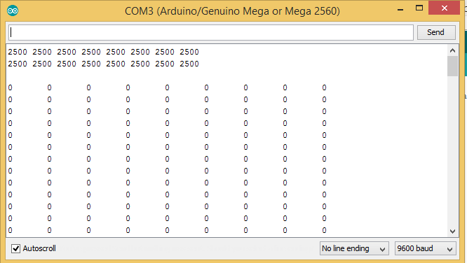
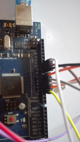
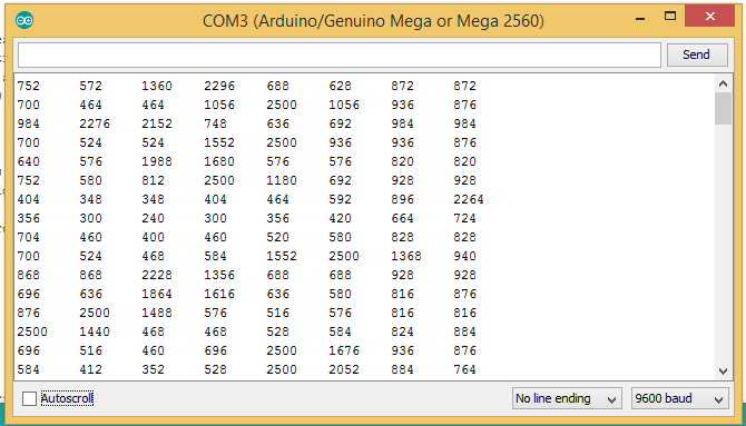
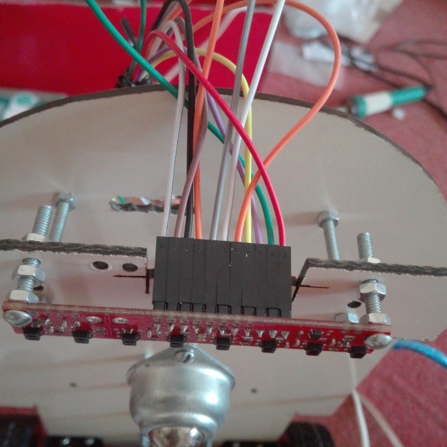
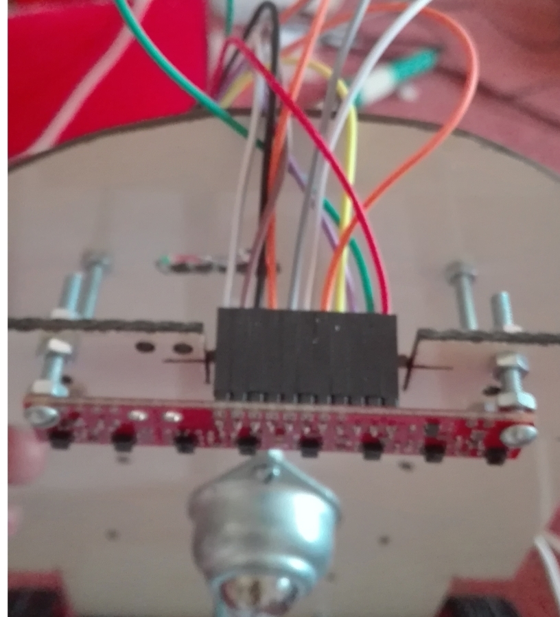
Until we can get your sensor working, I recommend using a simpler example to troubleshoot your sensors. Can you try running the “QTRRCRawValuesExample.ino” example and post a screen capture of the output as you did before? Do the values change when you pass the sensor over your line? Also, can you post a close up picture of the connections to the QTR-8RC senor that shows the pins you have connected to on the sensor?
-Derrill
hi
Digital pin 8 will be connected to what
Hi
Thanks Derrill
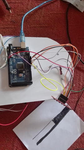
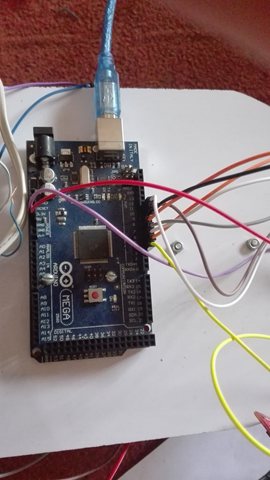
These are some pictures by running “QTRRCRawValuesExample” and also connection pins that i have connected…
Serial Comm Output
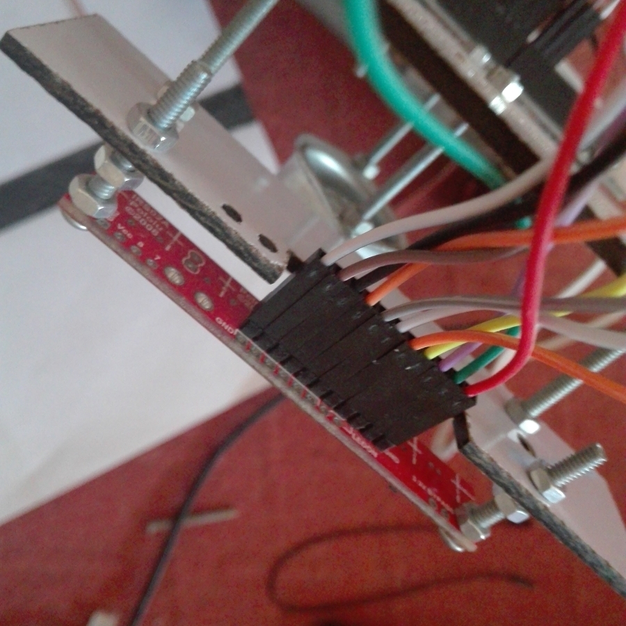
Digital pin 2 to digital pin 10 connected to Qtr senser
Qtr Sensor Connections
…
…
…
…
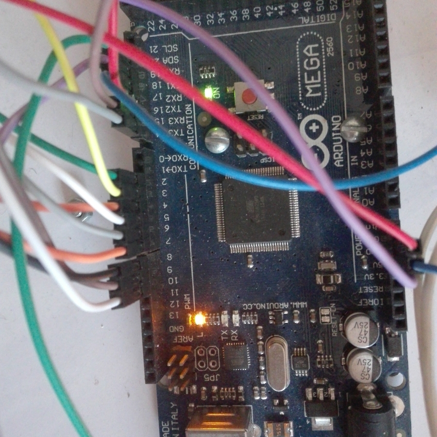
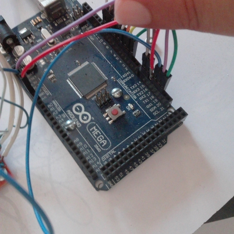
Mega Complete Connections Including Driver module pin connected with Digital pin 14 to 19
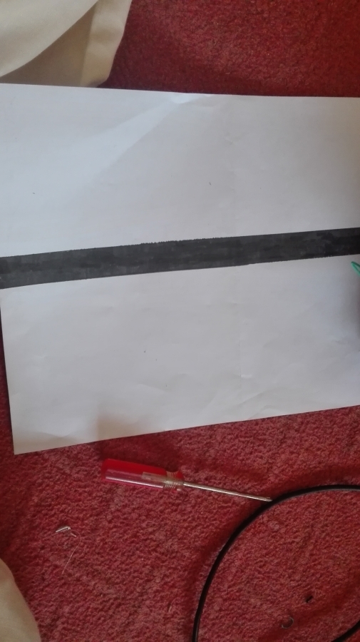
Line that I draw for Calibration
…

…
And again Thanks for helping me Derrill
The output of the QTRRCRawValuesExample is about what I expect from a working sensor. Can you try the “QTRRCExample.ino” and post the output as before? That demo does a calibration with the sensors, and when they are being calibrated (indicated by the user LED on the Arduino), you should be sure to pass each sensor on the board over your black line repeatedly so that each sensor passes over both the black and white surface.
By the way, I noticed that your line was made with a black marker. In my experience a line like that can give poor or inconsistent results due to the changes in line density. I suggest using black electrical tape to make your lines more uniform in size and IR reflectivity.
-Derrill