
Hi,
I have a problem with my U3V50ALV, my voltage input is around 14.7V and I put the potientiometer in order to obtain an output voltage around 20.9V. With no charge it’s OK. I would like to obtain an output current around 0.8A.
With a resistor load of 47 ohms, it’s OK with an input current of 0.77A and an output current of 0.450A. The efficiency is equal to 9.45/11.319 = 83.4%.
When i try with a resistor load of 30 ohms ( to simulate a current of 0.63A), the input current increases quickly to 5 A!! and the output voltage decreases under 12V and the circuit becomes very noisy!!
I don’t know why?
I will hope to obtain an ouput current of 0.75A in order to power 7x Cree XL Lamp module ( Vf around 2.9V/LED)?
Could you help me?
Thanks for advance,
marcounet
Hello.
Can you post some pictures of your testing setup? What kind of resistor(s) are you using to apply the load on the output, and what are you using to supply the input?
- Patrick
Hello Patrick,
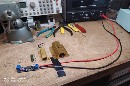
My set up is very basic ( see image in attached file) i use a workbench power supply (32V - 6A) and i connect input voltage via 20" cable power long.
The input voltage is set to 14.7V and the Power Supply current potientiometer is full clockwise (6A).
I soldered terminal blocks on the U3V50AHV circuit board and not used header pins.
I connected pure resistive load at output terminal block ( power rating resistors 10W to 100W in function of drawn current, for example the biggest one is 22 ohms 100W!! i put it in serie with other power resistor(s) to obtain different value of resistive load.
If i power U3V50AHV circuit with no load, it’s work fine with an output voltage of 20.9V and an input voltage set to 14.7 the input current is < 10mA.
I can repeat the same test on a second U3V50AHV board or change my workbench power supply? but i don’t understand where is the problem?
Thanks for your help,
Regards,
Marc,
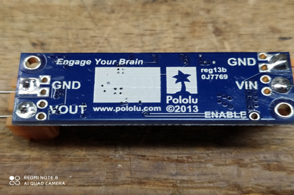
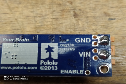
From what you described in your first post, it sounds like you might have been inadvertently shorting out the regulator’s output. Could you post some larger pictures that show the terminal block solder connections and how you had your resistors connected when you were having trouble? (Your first picture is very small, so it is hard to make out any details.)
- Patrick
Hi Patrick,
As suggested, please find images of terminal block solder connections
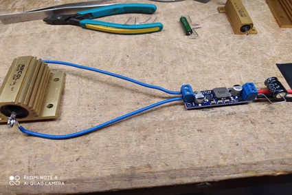
A) Today, i shortened input connections with wire less than 4" long - Vin = 14.7V , Vout no load = 21V
→ same problem!! with R= 33ohms ( Iout around 0.63A), the input voltage drop to 3.7V and the input current to 6A shortly
→ with R=35ohms (Iout around 0.59A), Vin=14.7, Iin=1.02A and Vout=20.93V
B) i use a second U3V50AHV purchased to Gotronic France
same wiring
same results!!
C) I use a new workbench power supply with same settings and same wiring
same results
it’s like the U3V50AHV circuit board has an output power limitation around 15W ? I don’t understand
Regards
Hi.
Since your input voltage is dropping, it seems pretty clear that this is an issue with your power supply not delivering enough current, not an issue with the regulator. I recommend checking the limit you have set and testing the supply with just a resistive load and no regulator attached.
I did also test a new U3V50ALV regulator with a 25ohm power resistor and a benchtop supply set to 14.7V out and a current limit of 5A, and I did not see any behavior like you mentioned.
-Claire
Hi,
I did also test two different workbench power supply with just a 22ohms - 100W resistive load and they deliver both a current around 1A with no problems ( current limit potentiometer full clockwise)!!
For information the second power supply can deliver 35V and current up to 45A!!
In your last reply, you did the test with a benchtop supply set at 14.7V, but with also the U3V50AHV output voltage set at 21V connected to your 25ohms power resistor?
If yès, could you indicate what is the benchtop power supply input current with your U3V50AHV when you did the same test ?
On my side, i did repeat the same tests with two different benchtop power Supply and two différents U3V50AHV circuit board and i obtained the same problems!! i suspect a problem of power limitation…
Thanks a lot for your help, it’s very important cause i 'm in charge of integration of electronics components in a ROV for an antarctic mission!!
Regards,
If you have a 45A power supply, you should focus on that. What happens when you try to use it?
-Claire
hello Claire,
Same problems with 45A power Supply, if i exceed an output power of 15W, the current increaseup to 6A and the input voltage drops to 3.7V!!
According to me, Pout = Pin x Efficiency, if i take an efficiency of 80%, i obtain :
Pout= Vout x Iout = Vin x I in x Efficiency
I in = (Vout x Iout) / (Vin x Efficiency)
with Rload = 22 ohms and Vout = 21V it gives
I in = ( 21 x 0.95) / ( 14.7 x 0.8 ) = 1.69A but the output power is around 20W and this power seems to high for the boost regulator voltage on the circuit!!
regards,
Since your supply is actually only outputting 3.7V, that should be used in the power calculation rather than 14.7V, which gives 6.7A. From that it can be seen that when your supply turns on and starts ramping up its voltage, at the instant it gets to 3.7V, the regulator needs the supply to output more than 6A to be able to generate 21V, but since the supply will not provide that power, the system gets stuck.
To fix the issue, we need to figure out why your supply is only outputting 6A. Can you verify that your supply’s current limit is not set to 6A by drawing more than that through a resistive load? Could you also try reconfiguring your test setup so you can turn on power to the regulator and then connect your load?
-Claire