I’m using a LSM303DLH 3D Compass and Accelerometer board from Pololu. I’m getting good magnetometer data, but the accelerometer data is giving me random numbers in the X and Y axis, and zero in the Z axis. This is with the board sitting still on a table. If I move the board, I see correctly changing values from the magnetometer, but the accelerometer data does not change correctly - the X and Y axis continue to be random, and the Z axis stays at zero.
I’m setting the CTRL_REG1_A to 0x27 and CTRL_REG4_A to 0x00, and I’m setting the MSB of the register subaddress to get the accelerometer to auto-step through the 6 output registers as I read them.
I believe I am configuring the device exactly as described in the ST application note, and I’ve tried many variations in configuration without any success with the magnetometer. Does anyone have any ideas? Could it just be a bad board?
But, I would attempt to send a register some settings and them read them back to make sure your communications are working as expected. Your problem could be caused by reading the wrong register(s).
Also, I send $C0 to CTRL_REG4_A - (block update in middle of read, LSB @ lower address, +/- 2g, no self test).
The readings from the accelerometer are 12-bit numbers “left aligned” in a 16 bit space. Are you shifting the result to the right by 4? If you are still having trouble, can you post your code?
Both of your suggestions helped. It helped to prevent updating the accelerometer data between bytes, and I did not notice the part about shifting the data right by 4 bits.
I am using an msp430 with some code I found on the TI website to bit-bang I2C to interface with the LSM303. I think there’s something wrong with the way this code drives the I2C signals, or at least the accelerometer in the LSM303 didn’t like the way it was done. Something was preventing the accelerometer from auto-incrementing its sub address, I believe (even though I was setting the msb of the sub address). Also, this I2C code does not have a function that can read a block of data and send a new sub address for each new byte read, so I added one.
Hi, I am facing the same problem, could you please provide some more information on how you fixed it?
lsm303dlh magnetometer data seems correct, updating every time. On the other hand, accelerometer data is fixed to some random values like 81 82 and 7F FF and the other axis is 0. I am using a TI part number CC2540 and the i2c bit-banging code… It could be the same problem that the auto-increment in the accelerometer qhe reading output register is not working…
Any help would be greatly appreciated!
Hi,
I am able to write a value into a register and read after the updated value of certain registers but that does not work with some others.
I am trying to write 0x27 in the CTRL_REG1_A but when I read the value it is a different one.
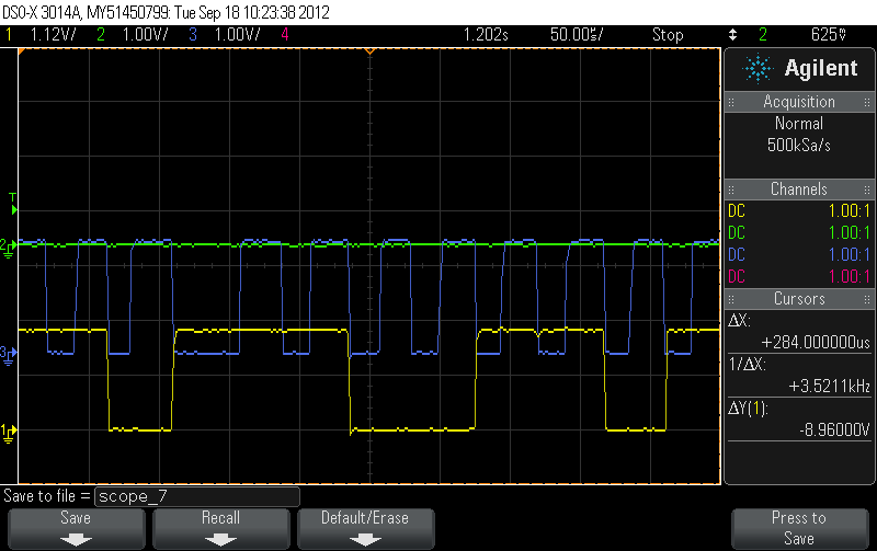
In the oscilloscope seems that maybe the hold time for the SDA is not meeting the requirements. But What should be the reason that only sometimes
that is happening if my read write functions are always the same?
Are the timing requirements for accelerometer and magnetometer registers the same?
thanks
The LSM303DLH combines two dies into a single package, so the I2C circuits for the magnetometer and the accelerometer are probably independent. There have been other reports that the timing characteristics of the two are different. What frequency are you clocking the I2C bus with? Does it become reliable if you use a lower frequency?