I am trying a simple test to turn a wheel attached to a Pololu 29:1 Metal Gearmotor 37Dx52L mm with 64 CPR Encoder (product #1443) one rotation using an Arduino UNO. (This means the motor shaft would turn 29 times.) I am using only encoder channel A. The program below uses an interrupt to look for a falling signal on the encoder channel. The program spins the wheel until the encoder position reaches 464 (ie 16 times 29). Then it waits five seconds and spins another rotation.
Here’s the problem: On the wheel’s first rotation, the wheel overshoots its mark by about 25%. Then on subsequent rotations, it undershoots its mark by about 5%, but sometimes more. To try to see what’s going on, I modified the program to store the time that each interrupt was triggered in an array. Generally speaking, the times between triggers are consistent, although it takes a few turns of the motor shaft to get up to speed, so the time between the initial readings is longer. If the motor were consistently overshooting its mark, I would guess it’s coasting at the end, but it only overshoots on the first rotation.
Note, that if you run the code, you will need to start the motor by typing something in the serial window. There will then be a five second delay before the motor spins.
Any help would be appreciated.
/*
 RotaryEncoder sketch

 This sketch: (1) rotates a wheel one rotation, (2) prints the value of encoder A, (3) delays the program 5 seconds, and (4) repeats

 Hardware:  (1) Pololu 29:1 Metal Gearmotor 37Dx52L mm with 64 CPR Encoder (#1443) and (2) Arduino UNO

 Note... the program reads only encoder A and uses just the falling edge of the channel.
 Using just a single edge of one channel results in 16 counts per revolution of the motor shaft.
 Thus, the frequency of the A output is 16 times the motor rotation frequency (ie 16 times 29 = 464).
 */
#define CH_1_DIR_PIN 6  //pin to set the direction of roatation
#define CH_1_PWM_PIN 9   //  pin to set the speed of rotation

const int encoderPinA = 2;  //encoder A output to pin 2
const int encoderStepsPerRevolution = 464; // 16 times 29 (motor frequency)

int Pos = 0, oldPos = 1;
volatile int encoderPos = 0; // variables changed within interrupts are volatile

void setup()
{
  pinMode(CH_1_DIR_PIN, OUTPUT);  // motor direction pin is output
  pinMode(CH_1_PWM_PIN, OUTPUT);  // pwm pin is output

  pinMode(encoderPinA, INPUT);  //  encoder pin is input
  digitalWrite(encoderPinA, HIGH); //enable pullup resitor
  Serial.begin(9600);

  digitalWrite(CH_1_DIR_PIN, HIGH);  // motor direction is clockwise
  while (!Serial.available()){  //don't start motord until a key on the keyboard is hit.
  }
  attachInterrupt(0, doEncoder, FALLING); // encoder pin on interrupt 0 (pin 2)
}

void loop()
{
  analogWrite(CH_1_PWM_PIN, 100); // start motor turning

  /********************
   The following code turns off the interrupts while getting data from encoderPos */
  uint8_t oldSREG = SREG;  //save status register
  cli();  //turn off interrupts while getting data from encoderPos
  Pos = encoderPos; //get data
  SREG = oldSREG; //restore status register and turn interrupts back on
  /********************/
  if(Pos != oldPos){  // See if encoder A has changed value
    if (Pos % encoderStepsPerRevolution == 0){  // See if the wheel has turned one revolution
      analogWrite(CH_1_PWM_PIN, 0); //turn motors off
      float angle = (Pos % encoderStepsPerRevolution)*(360/(float)encoderStepsPerRevolution);  // calculate angle (which should be zero)
      Serial.print(Pos, DEC);
      Serial.print (" ");
      Serial.println (angle);
      delay(5000);
    }
    oldPos = Pos;
  }
}

void doEncoder()
{
  encoderPos++;    // count up if both encoder pins are the same
}
I don’t see any obvious problems with your code. How are you measuring overshoot or undershoot? If you are determining overshoot/undershoot by looking at your motor, can you post a video that shows the behavior you are getting?
That was a useful video; I am not sure why there are two different behaviors, but I suspect that the reason can be found in the setup portion of your code.
The gear ratio of those gearmotors is actually slightly more than 29:1. More accurately, it is 367500/12600, which is approximately 29.167. So, if you update the “encoderStepsPerRevolution” value, it might address the undershooting.
By the way, what motor driver or motor controller are you using to control the power to your motor? Can you send me a schematic of your connections? If you are using one of our products, I might be able to see if I can reproduce the problem.
We looked into this further today, and counted the gear teeth in the gearbox of one of our #1443 gearmotors. We found that the gear ratio is actually exactly 30:1.
Unfortunately, without telling us, the manufacturer of our gearmotors started replacing one of the gears used in some variants of our 37D gearmotors, which changed the overall gear ratio of the gear train on those specific gearmotors. We plan to update the web pages of the affected gearmotors soon. We have arranged for them to inform us of any future changes.
That makes sense. Any theory as to why the first rotation blows past the one revolution mark? I gather it won’t affect us but I am curious what might be different about the first turn. Thanks.
I’ve talked to a few people here and we are not sure why you are getting that initial overshoot. Can you tell me what motor driver or motor controller you are using? I would like to try this out myself, and if you are using one of our products, I want to get it as similar to your setup as you can. Also, have you gotten a chance to update the “encoderStepsPerRevolution” value?
We are using a Dagu 4 Channel 5-12V, 2A Brushed DC Motor Controller with a 7.4v LiPo battery. We recently ordered one of your controllers and will report back.
FYI: We also ordered some of your new optical encoders for your micro motors with extended shafts. We want to see if we can use those motors instead of the 37Ds. Hopefully, our microcontroller will be able to read the encoder’s analog signal without a hitch, assuming we optimize the placement of the encoder wheel as described in the installation notes. Needless to say, we are not sure how to build a simple comparator to convert the signal to a square wave (but doing so sounds like it would be a fantastic extension of the project).
Hey
I decided to join this conversation cause I have similar problem as jonathang. Im trying to turn the wheel by one or more rotations and as well as jonathang’s motor overshoots while making turn. Im using different encoders, this one: pololu.com/product/2213
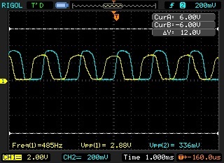
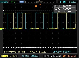
At the beginning I connected signals from encoder straight to my atmega8 and then I decided to use comparators hoping that changing sinusoid signal to square will solve my problem but it didnt, actually results was more or less the same I think.
Thank you for posting the video. Strangely it looks like when you command the motor to do only one revolution you are getting a definite overshoot, but then when you command the motor to do four revolutions it undershoots. This might be due to a combination of a slight undershoot caused by the number of counts per revolution used in your code being a bit off and a larger overshoot caused by the motor not stopping immediately when it is commanded to.
As Jon mentioned in a previous post, some of our motors with encoders and extended shafts do not have their exact gear ratios listed on their product pages. The gear ratio for our 50:1 micro metal gear motors is actually about 51.45:1. We just updated the product pages for all of our micro metal gearmotors with extended shafts, so they should now list a more exact ratio. If you adjust the gear ratio used in your program does the motor start to overshoot when making four revolutions?
As for the motor causing an overshoot by not stopping fast enough, what motor controller or driver are you using? Does it operate in drive/brake or drive/coast mode? In your program it looks like you are just monitoring the number of counts of the encoder and then commanding the motor to stop after a set number. If you want to accurately stop the motor after exactly one revolution you will likely need a more complex control loop.
I just applied your advises and its seems that it works much better. I just added simple code to stop motor more gently than I was doing before and corrected gear ratio and its stops almost at the same point in every rotation. I think I just need to improve a little bit more my control loop and it should work perfect.
Thank you very much Claire for your help. Now I could just relax and start to code