I am using a non-Arduino board to read the IMU9 and IMU9-v2. The I2C code I was using was working great with the IMU9 and I recently bought 6 IMU9-v2 in order to replicate the boards I am using. However, I have not managed to read the IMU9-v2, only the IMU9.
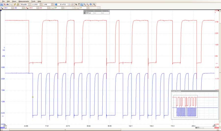
What I am doing for now is rather simple, just trying to read the WHO_AM_I register. Since I am using a non-Arduino board, I don’t want to post any code, instead, I am posting the actual waveforms obtained during the transaction from an oscilloscope. What seems to be happening is that the IMU9-v2 does not seem to acknowledge on the 9th clock cycle (i.e., it does not draw the SDA line low). The clock freq is 400KHz.
The code detects the lack of ACK and fails.
Any idea why this occurs?
By the way, I have tried this to 4 different IMU9-v2 modules and I get consistent results.
I’m looking at the same upgrade – I got a IMU9-v2 during the black friday sale, but it’s in the queue of things to actually integrate…
Does the IMU9-v2 use the same address for the chips as IMU9?
The description for IMU9-v2 says:
The address is different and there are minor details in terms of the Gyro the sample rate and bandwidth terms but the rest is the same.
All in all, if the interfacing worked as before, upgrading would be less than an hour’s work, but the I2C problems I have run into have really killed my timeline.
By the way, I have made a bit of progress and I can now talk to the gyro, at least and get it to reply to reading the register. However, I am getting very inconsistent results. I have to try reading the register several times before it will start responding and higher speeds (i.e., 400K) are more unreliable than others. By the time I start reading data, there are so many bit errors that the results are unusable. When looking at the waveforms on the scope, it seems that the new module has a higher capacitive load which makes the driving circuit harder to do, even at 100K.
I am close to giving up to that portion of my project; wish I had bought all the modules I needed before the upgrade!
I’m sorry you’re having trouble using the MinIMU9 v2. It sounds like you’re mainly having trouble with the L3GD20; have you been able to communicate with the LSM303DLHC successfully, or is that also problematic?
If you can simplify your code to something minimal that shows the problem, I would still like to see it (if only to check that you are using the right device and register addresses). Also, what is the scope capture you posted supposed to show? It looks like 0x6B 0x6D (01101011 01101101), which I don’t recognize as anything the gyro would respond to.
Either that, or the pull-up is weaker. Try adding a 2.2k pull up on each of sda and scl. It will use more current and clean up the signal and probably not kill anything (current will still be less than 5 mA even if the existing pull up is 2.2k already)
So the problem is solved; as jwatte recommended, I added an extra 2.2k pull-up, which cleaned up the waveform significantly, so now i can read the sensor fine with no unexpected behavior. I can go up to 400Khz clock rate with no issues.
I’m glad to hear that solved your problem. I didn’t initially suspect the pull-ups because we’ve successfully used the IMU with 3.3V controllers without any problems. To make sure your board was assembled correctly, if it’s not too much trouble, could you try measuring the resistance between SCL and VIN and SDA and VIN without anything else connected? Both resistances should read 4.7k.
Hello, I too am having a hard time reading the Gyro output. I did attach the 2.2Kohm resistor between SDA and VIN, and SCL and VIN. This did not help. I can read the Accel, and Magnetometer fine except for the Magnetometer Temperature output is way to low. The l3gd20 is able to do both SPI and I2C. I saw the registers for SPI but how do you tell it to send in I2C mode.
P.S. I am writing my code in C for the 644P uC.
If you could post the configurations of the gyro registers that would probably help.
thanks
The L3GD20 is in I2C mode whenever the CS pin is deasserted (high), and the MinIMU-9 pulls the CS pin high. For an example of the minimum configuration required, I suggest looking at our Arduino L3G library. I can also take a look at the relevant part of your code if you post it here.
As for the magnetometer temperature output, I think it is better for tracking relative changes than as any kind of absolute temperature measurement (or at least there might be an undocumented offset). My general impression is that the temperature sensor is there just to help compensate the magnetometer readings internally, and the output of the temperature sensor is made available as a “bonus”.