Hello,
I have been trying to read the increment of the encoder that is attached to a dual shaft motor. I had to amplify the output signals of the encoder to 5V. Since the op-amp is not ideal it is clipped at 4.5-4.7V. I initialized the digital input pins with encoder functions. The code aims just to test the encoder. However on the serial monitor I only see zeros and ones. Only for two instances I saw the values increment. Can you help me with my problem. The code is below.
char send_buffer[32];
int ticks;
int main()
{
	serial_set_baud_rate(9600);
	encoders_init(IO_D7, IO_D4,IO_C1,IO_C2);
	while)(1)
	{
		ticks = encoder_get_counts_m2();  //position data
		while(!serial_send_buffer_empty());
		int message = sprintf(send_buffer,"%d \r\n", ticks);
		serial_send(send_buffer, message);
	}
}
Hello.
I am sorry you are having trouble reading your encoders. Thanks for posting your code; it looks fine.
The encoders_init() function has four arguments (named m1a, m1b, m2a, and m2b) which are the four pins that the wheel encoders are connected to. The initialization function is designed with the intention that when motor M1 is spinning forward, pin m1a will change before pin m1b. However, it is difficult to get those connections all correct on the first try, and you might have to experiment. Can you try checking your connections to ensure your script is properly set up to count ticks?
If that does not help, can you tell me more about your system? What microcontroller are you using? How are you supplying power? Can you post pictures that clearly show how you have your optical encoder connected? Can you also verify that your encoder channels are outputting a usable signal by measuring their outputs when the motor is rotated by hand? If you have access to an oscilloscope, you should use that and look at the waveform and its magnitude. If you do not have access to an oscilloscope, you might try using a multimeter.
-Jon
Hello,
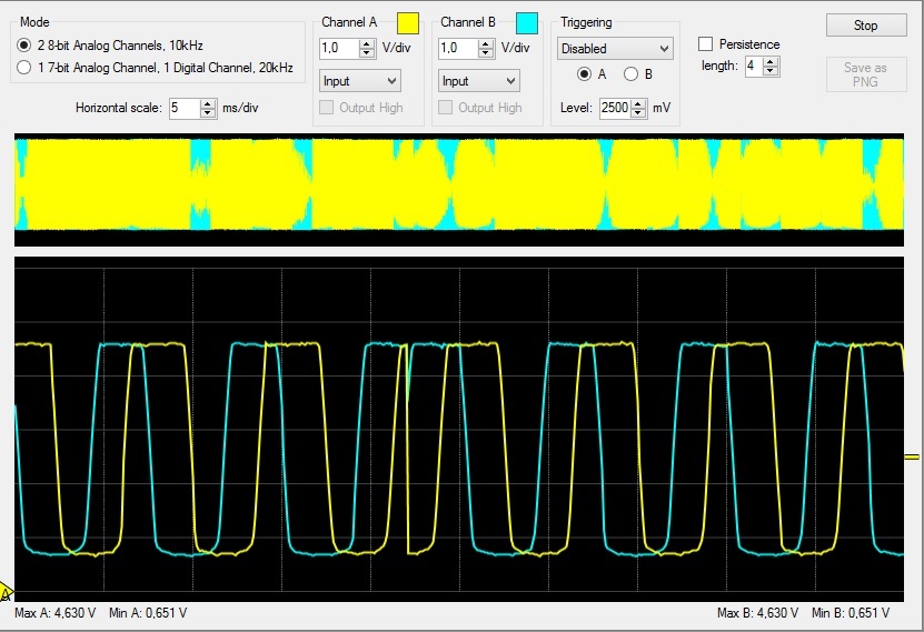
I am using a baby orangutan b-328 microcontroller. The encoder signals are amplified with a MCP6004 op-amp. I supply the power to the breadboard using a power supply module 3.3V to one line 5V to the other. I power the encoder and orangutan from those two lines respectively. Below are the pictures from the circuitry and the SLOscope window for monitoring signals.
Those waveforms look good. Did you try switching around your encoder connections like I described in my last reply?
-Jon
Hi Jonathan, I purchased a magnetic encoder to eliminate the need for signal conditioning. I am supplying 5V power the encoder and the waveforms look good. But still I am having the same issue regardless of checking the connections.
Another interesting thing is that when I remove the ends of the cables from the encoder and touch with my hands it picks up something and the ticks increment just fine.
It incremented once when I added and then commented out a “set_digital_input” function for the encoder pins but it was a one time thing.
Can you post pictures that clearly show the soldered joints on your magnetic encoder board and the connections you are making to your Baby Orangutan? If your code is any different, please also include your modified code in your reply.
-Jon
Hi Jon, the board is not currently with me right now but I checked the soldered connections and orangutan connections with a multimeter before I connected them to board. They checked out. I will post the pictures tomorrow.
Hi Jon. The pictures are attached.
Can you measure the voltages of PC1 and PC2 on the Baby Orangutan as the magnetic disk is turned and see if those voltages move between zero and 5V?
-Jon
I measured and also views from SLOScope. The voltages move between 0-4.7ish. sometimes 5. I observe increment at only very small perturbations. The waveforms look good. What I do not understand is I had this issue with another encoder and I can sometimes see some increment in the Orangutan side. Have anyone encountered this zeros and ones issue before with these encoder? It seems very random.
Getting 0s and 1s returned from encoder_get_counts_m2() could mean that one of the two encoder channels is not working and is just at a constant value, or that one of the two Baby Orangutan pins is not correctly or consistently registering changes in voltage. We can test for the latter case by switching your inputs on the Baby-O. Can you try moving your encoder outputs to PD7 and PD4, and modify your code to use encoder_get_counts_m1() instead of encoder_get_counts_m2()?
Also, can you describe where exactly in your setup you connected your SLO-scope pins to confirm that the signals were good?
-Jon